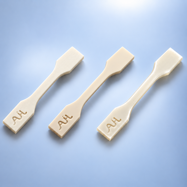
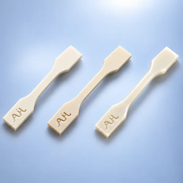
PLA
Example partsConcept models, enclosure fit-checks and presentation prototypes.
Selection focusChoose PLA for quick, economical prototypes. Check temperature exposure and handling loads before specifying it for functional use.

3D Printing
Extruded thermoplastic layers for rapid, economical prototypes.
Fused Deposition Modeling (FDM) extrudes heated thermoplastic filament in thin beads, stacking layers to form a part. FDM is economical for early prototypes, large bulky geometry, and fixtures where surface cosmetics are secondary to speed and cost.
FDM feeds thermoplastic filament through a heated nozzle and builds the part layer by layer. Follow the process from slicing to final inspection.
Review wall thickness, overhangs, mating features and the expected load direction. Orient the part with layer bonding and surface finish in mind. Set layer height, perimeters, infill and supports, then slice the model into toolpaths.
Dry the thermoplastic filament as required for the selected grade, then load it into the feeder. Prepare the build surface and set the nozzle, bed and chamber temperatures as required by the material and printer.
Drive gears feed filament into the heated nozzle. The nozzle deposits molten material along the sliced paths, forming perimeters and infill. Each new bead bonds to the material beside and beneath it. The nozzle and build platform shift by one layer height relative to each other, and the cycle repeats.
Let the part and build plate cool as required before removal. Detach the part without forcing it, especially at thin walls and small features.
Remove breakaway supports or dissolve soluble supports where used. Sand or finish specified surfaces as needed, and review any planned secondary operations, such as drilling or adding inserts.
Check critical dimensions, mating features and visible defects such as warping, under-extrusion or layer separation. Verify the agreed finish and drawing requirements before release.
Typical planning values for filament FDM. Fine-detail values assume a 0.4 mm nozzle and do not apply to every large-format setup. Build dimensions below are separate manufacturer examples, not a combined envelope or confirmed in-house machine list.
| Parameter | Capability |
|---|---|
| Max. Build Envelope | Large-format market references (X × Y × Z): 1,005 × 1,005 × 1,005 mm (BigRep ONE); 1,800 × 600 × 660 mm (Modix BIG-180X GEN5); 970 × 1,030 × 2,000 mm (Modix Everest GEN5). AIHFABS availability and usable one-piece size require project review. |
| Layer Thickness | 0.16–0.28 mm typical prototypes; 0.08–0.12 mm for finer surfaces. Large-format reference: 0.3 / 0.6 / 1.0 mm, depending on nozzle and platform. |
| Minimum Wall Thickness | 0.8–1.2 mm recommended with a 0.4 mm nozzle (2–3 extrusion lines); large-format nozzles require thicker walls. |
| Minimum Feature Size | 0.8 mm recommended with a 0.4 mm nozzle; increase for large-format extrusion and load-bearing details. |
| Typical As-Built Tolerance | ±0.5 mm or ±0.5%, whichever is greater, on suitable geometry; large parts, warp-prone materials and assemblies require drawing review. |
| Surface Roughness | Ra 10–25 µm indicative for standard FDM surfaces; orientation, layer height and nozzle affect results. Large-format layers may be substantially rougher. |
| Surface Finish | Visible layer lines; sanding, filling, priming and painting available by material. |
| Supports | Breakaway or soluble supports for overhangs and bridges; availability depends on material and machine. |
| Lead Time | From 24–48 hours for suitable small parts; meter-scale parts require a project-specific build and finishing schedule. |
Large-format manufacturer references: BigRep ONE · Modix GEN5 specifications. Material, nozzle, orientation and support requirements determine usable part size.
PLA, PETG, ABS, ASA, nylon, and carbon-filled blends. Chamber heat is used when the grade needs it.
Example partsConcept models, enclosure fit-checks and presentation prototypes.
Selection focusChoose PLA for quick, economical prototypes. Check temperature exposure and handling loads before specifying it for functional use.
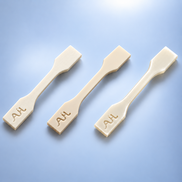
Example partsSensor mounts, cable guides and light-duty fixture brackets.
Selection focusChoose PETG for toughness and good layer bonding. Check stiffness and creep under sustained load.
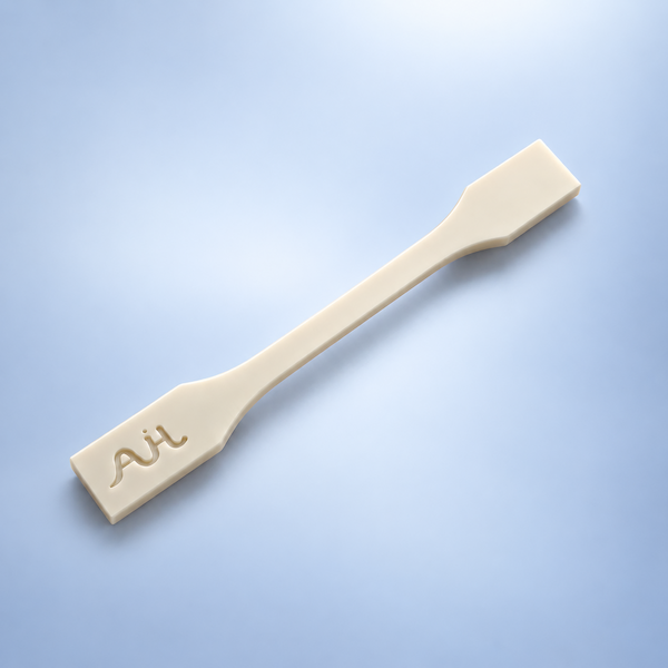
Example partsElectronics housings, protective covers and assembly fixtures.
Selection focusChoose ABS when toughness and heat resistance matter. Review warping risk on large, flat parts and verify critical fits.
Tell us the material and application requirements for your part.
See how FDM parts look as printed and what changes with support removal, sanding, painting, or threaded inserts.
Visible layer lines remain after any required support removal. This finish suits shop aids, fixtures, and internal mock-ups where surface appearance is secondary.
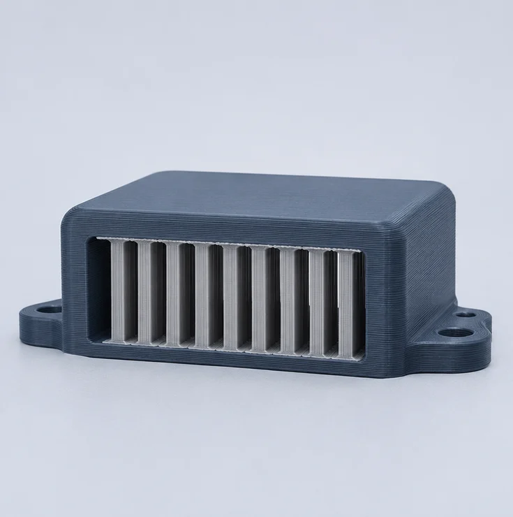
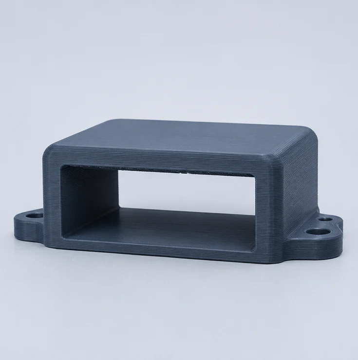
Remove temporary supports from overhangs and accessible recesses. Light contact marks may remain where the supports touched the part.
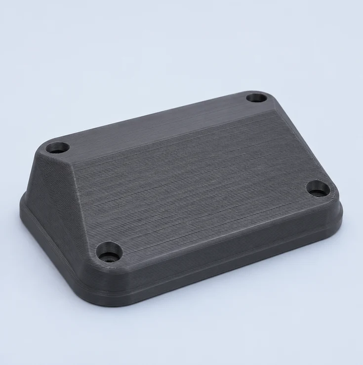
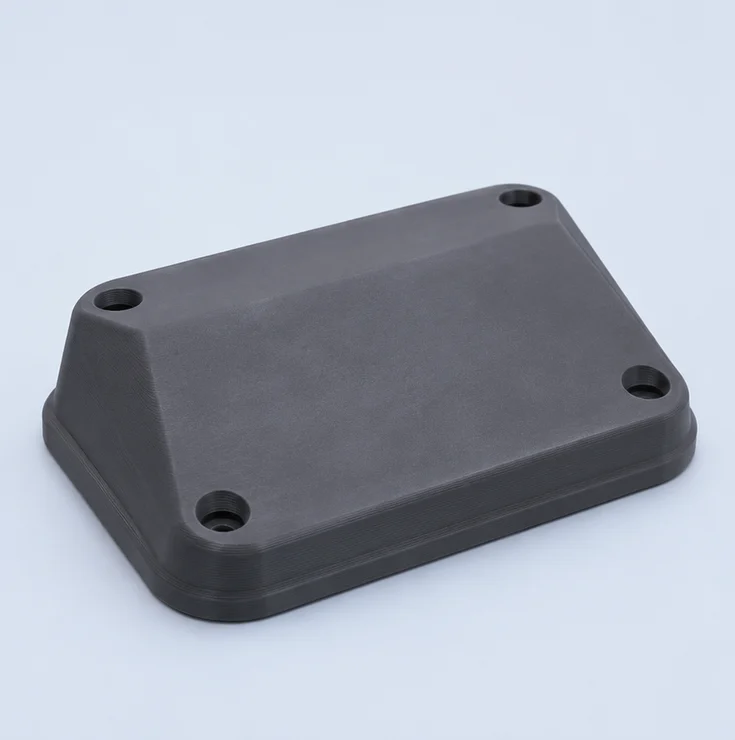
Sand raised layer ridges and fill low spots on visible faces before painting. Mark mating surfaces and sharp edges that need to retain their dimensions.
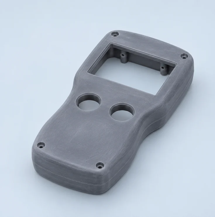
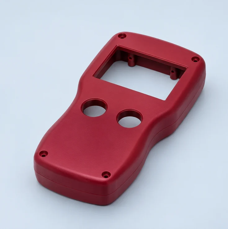
Apply a compatible primer and topcoat to prepared faces. Specify the color and sheen, and mark holes or mating surfaces that need masking.
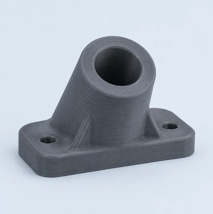
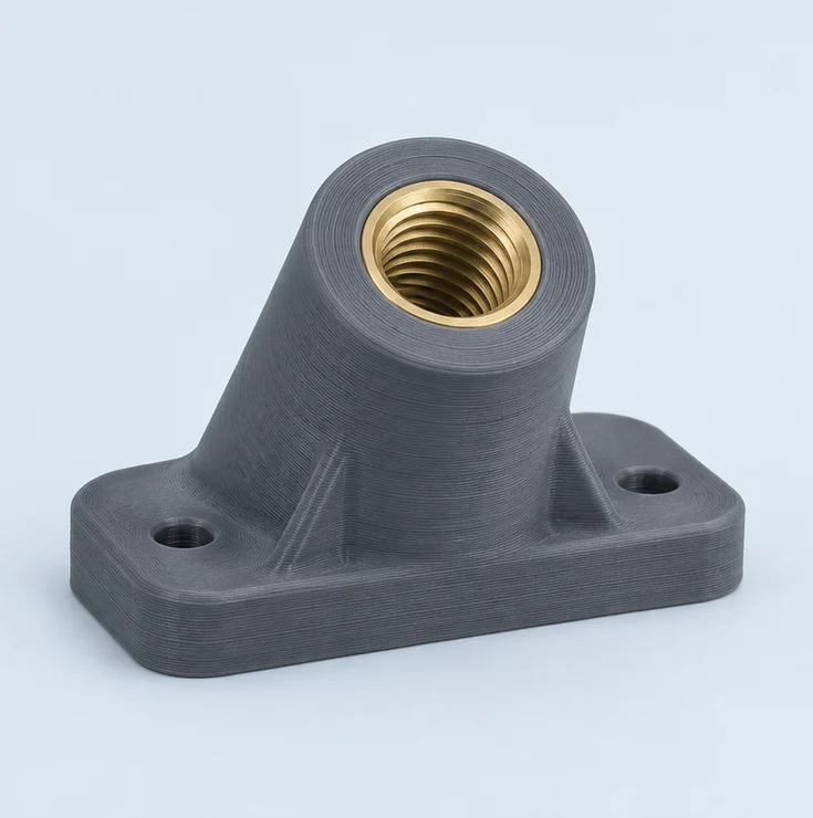
Review direct tapping or a threaded insert to suit the material, wall thickness and assembly requirements. Specify the thread size and engagement depth.
Compare FDM with SLA, DLP and SLS / MJF by feature detail, material performance, surface finish, cost and lead time.
Swipe horizontally to view the full comparison.
| Comparison Factor | FDM Filament Printing | SLA Resin Printing |
|---|---|---|
| XY Detail | Nozzle width limits fine text and narrow grooves | Fine features and smooth curves |
| Typical Tolerance | ±0.5 mm or ±0.5% For FDM-appropriate geometry | ±0.2 mm on well-supported features |
| Max Build Envelope | Varies by machine Large-format options on request | Up to 1,400 × 700 × 500 mm X × Y × Z |
| Layer Thickness | Varies by machine and setup | 0.05–0.25 mm G1400-P+ equipment reference |
| Build Speed & Batch Throughput | Quick iterations for simple parts Infill and supports affect print time | Longer scan paths take more time |
| Functional Performance | Thermoplastics for fixtures and functional prototypes Often weaker across layers | Properties vary by resin grade Check load and flex requirements |
| Surface Finish | Visible layer lines Optional sanding or coating | Smooth as printed Sanding, painting or coating |
| Supports & Post-Processing | Breakaway or soluble supports for overhangs No UV post-cure | Wash, UV post-cure and remove supports |
| Finished-Part Cost | Often economical for simple parts Finishing can add cost | Cost varies with scan time, resin and finish |
| Lead Time | 24–48 hours depending on part size | 24, 48 or 72 hours after file approval Depends on part size and finishing |
| Comparison Factor | FDM Filament Printing | DLP Resin Printing |
|---|---|---|
| XY Detail | Nozzle width limits fine text and narrow grooves | Crisp XY detail Pixel edges on some curves |
| Typical Tolerance | ±0.5 mm or ±0.5% For FDM-appropriate geometry | ±0.2 mm on supported geometry |
| Max Build Envelope | Varies by machine Large-format options on request | Depends on the assigned machine Typically desktop to mid-size platforms |
| Layer Thickness | Varies by machine and setup | Confirm for your project |
| Build Speed & Batch Throughput | Quick iterations for simple parts Infill and supports affect print time | Parts share each layer exposure |
| Functional Performance | Thermoplastics for fixtures and functional prototypes Often weaker across layers | Resin grade determines stiffness and toughness. Check load and flex requirements.Thermoplastics for fixtures and functional prototypes Often weaker across layers |
| Surface Finish | Visible layer lines Optional sanding or coating | Smooth as printed Vapor polishing or coating available |
| Supports & Post-Processing | Breakaway or soluble supports for overhangs No UV post-cure | Supports required on overhangs Wash, post-cure and remove supports |
| Finished-Part Cost | Often economical for simple parts Finishing can add cost | Packed builds can lower unit cost |
| Lead Time | 24–48 hours depending on part size | From 48 hours |
| Comparison Factor | FDM Filament Printing | SLS / MJF Nylon Printing |
|---|---|---|
| XY Detail | Nozzle width limits fine text and narrow grooves | Fine text and small grooves can lose definition |
| Typical Tolerance | ±0.5 mm or ±0.5% For FDM-appropriate geometry | ±0.3 mm or ±0.3% Planning tolerance |
| Max Build Envelope | Varies by machine Large-format options on request | SLS: 645 × 325 × 520 mm MJF: 380 × 284 × 380 mm Planning dimensions |
| Layer Thickness | Varies by machine and setup | Confirm for the selected machine and material |
| Build Speed & Batch Throughput | Quick iterations for simple parts Infill and supports affect print time | 3D nesting for batch production Cooling adds time |
| Functional Performance | Thermoplastics for fixtures and functional prototypes Often weaker across layers | PA12 for functional housings and snap-fits Grade determines stiffness and toughness |
| Surface Finish | Visible layer lines Optional sanding or coating | SLS: Matte, slightly grainy Vapor smoothing or tumbling MJF: Fine grain Dyeing or vapor smoothing |
| Supports & Post-Processing | Breakaway or soluble supports for overhangs No UV post-cure | Powder bed supports parts No separate supports Trapped powder needs an escape path |
| Finished-Part Cost | Often economical for simple parts Finishing can add cost | Dense builds can lower unit cost Depends on packing and finish |
| Lead Time | 24–48 hours depending on part size | Express from 48 hours Standard options: 72 hours or 5 days |
SLS / MJF are grouped for nylon part selection. Their processes and available grades differ. Final dimensions, tolerance, price and lead time depend on your CAD, material and finish.
Explore the equipment and workshop behind our Fused Deposition Modeling 3D printing service.
Equipment & Manufacturing
We select equipment based on part size and filament requirements, then plan build orientation and supports around load direction and surfaces that need a clean finish.
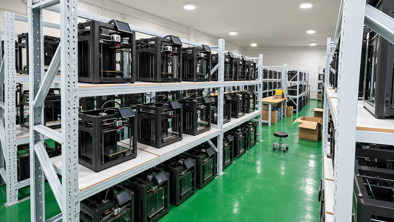
AI-generated equipment illustration.
Manufacturer reference dimensions; available equipment and usable one-piece size are confirmed for each project.
FDM Equipment References · Build Volume (X × Y × Z)
256 × 256 × 256 mm · 0.4 mm hardened-steel nozzle · 300°C maximum hotend
Manufacturer specifications ↗1,005 × 1,005 × 1,005 mm
Manufacturer specifications ↗1,800 × 600 × 660 mm
Manufacturer specifications ↗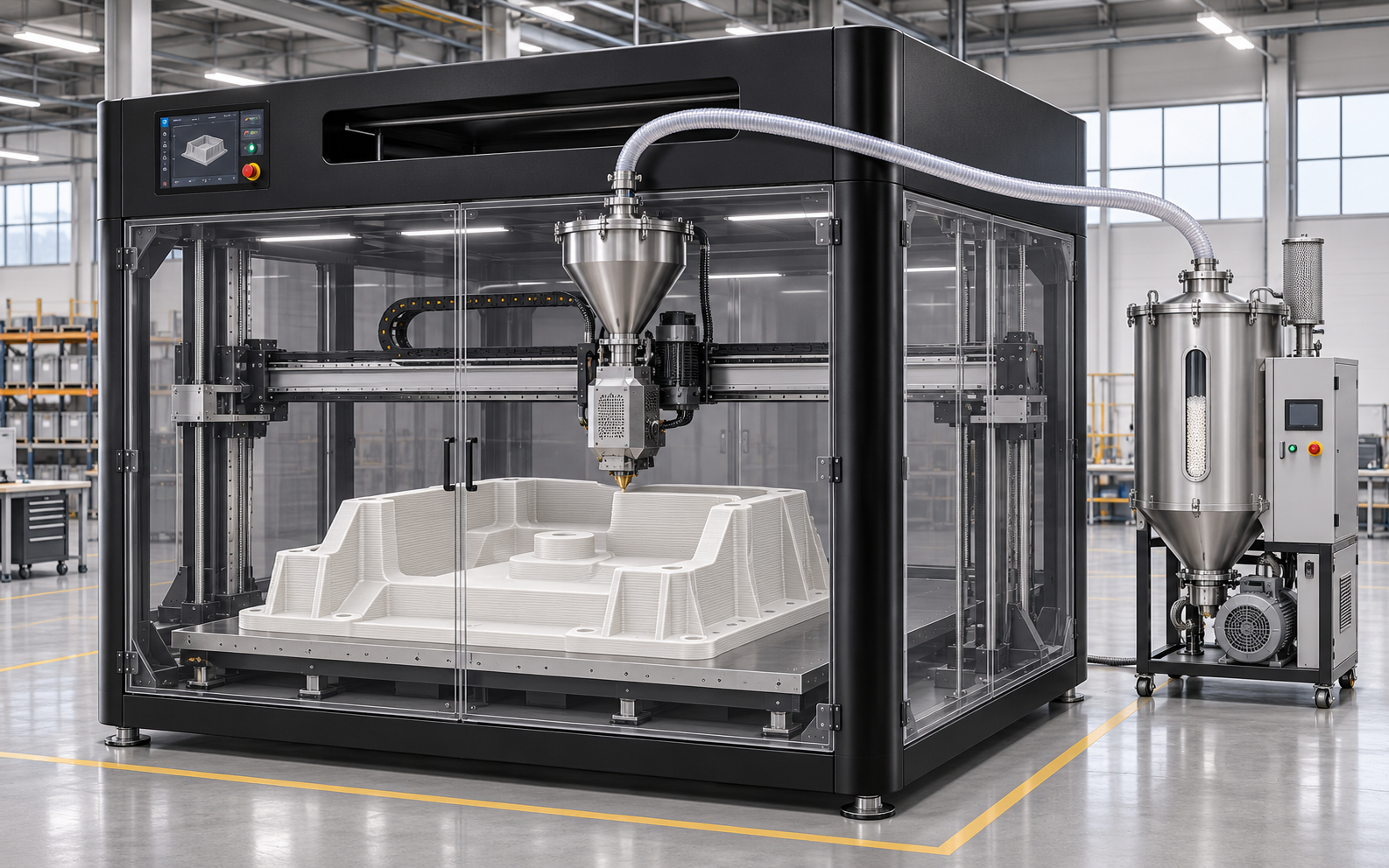
AI-generated pellet-extrusion (FGF) illustration; filament machine specifications are listed separately.
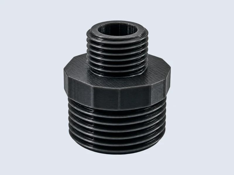
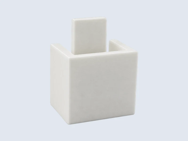
Explore FDM part examples, from threaded adapters and lever samples to textured and openwork forms.
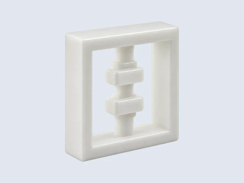
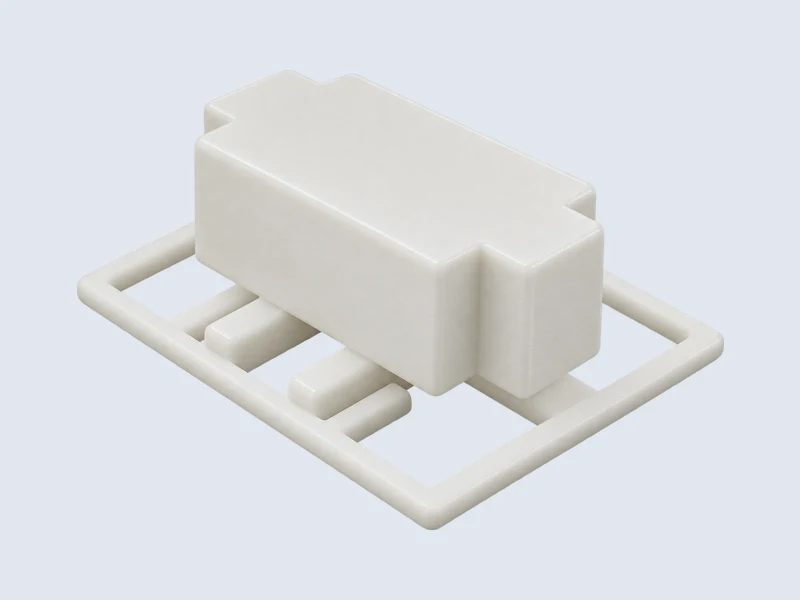
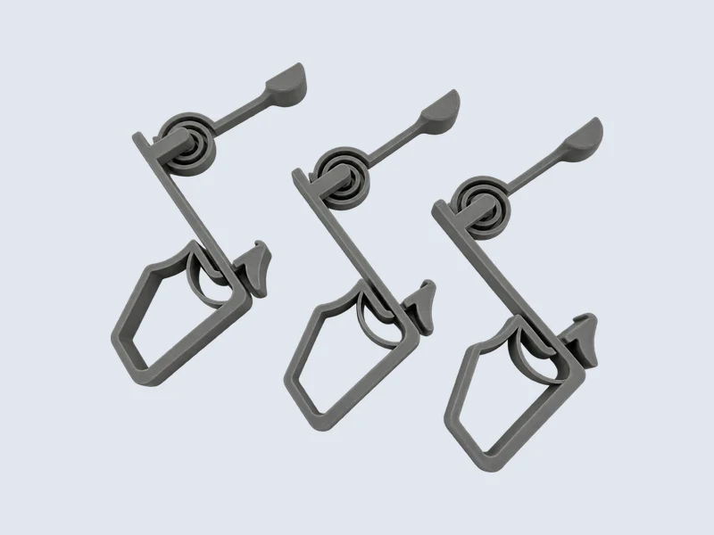
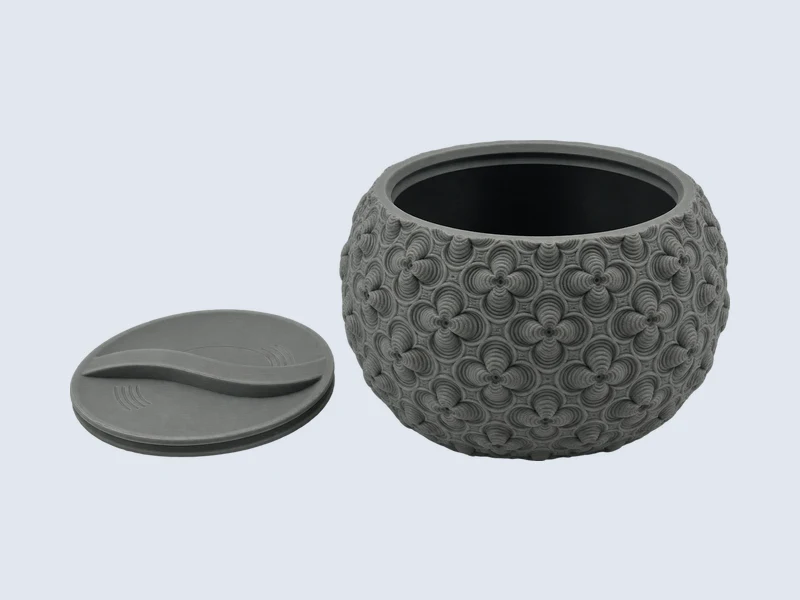
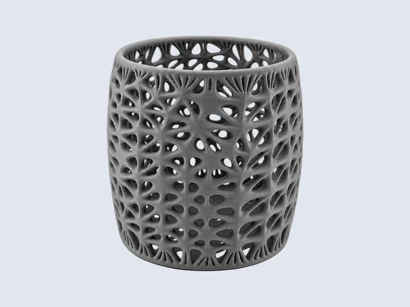
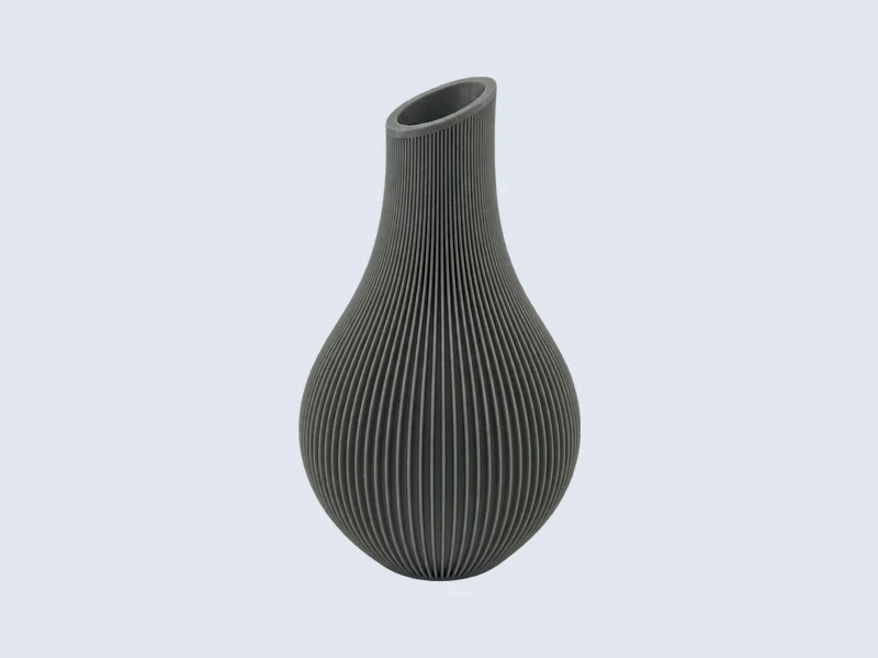
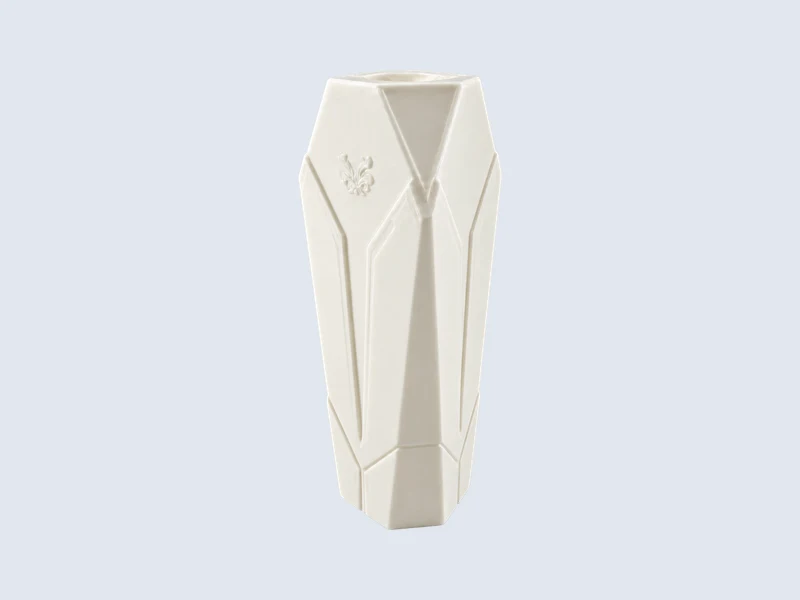
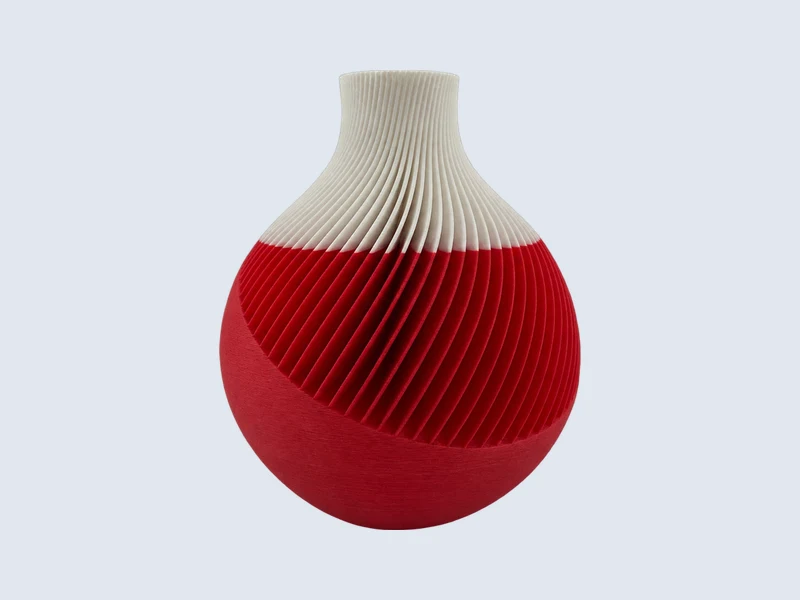
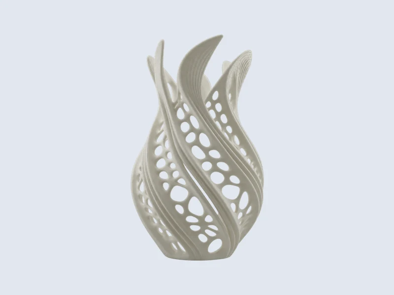
Have an FDM part ready for manufacturing review?
Upload Your DrawingsApplications Across Industries
Use FDM to check fit and assembly, build functional prototypes, and produce custom jigs and fixtures for the shop floor.
From automotive fit-check models to electronics enclosures and robotic tooling prototypes, we select the filament and build orientation based on how the part will be used.
Explore All IndustriesFor functional parts, share expected loads, operating temperatures, and critical mating dimensions so we can review material and build orientation.
See how filament, print time and finishing affect the cost of your FDM parts.
Each example is one open-top rectangular tray with 2 mm walls and a 2 mm base, without a lid or extra supports. Prices use the actual solid wall/base volume, not the bounding box. All three samples reach the current $2.99 minimum unit price. Optional finishing and shipping are excluded. Actual CAD geometry and print settings affect the final quote.
Share your CAD file, filament requirements, order quantity and target delivery date. Specify critical fits, cosmetic faces, threaded features and any inspection requirements.
Filament grade, part size, layer height, walls, infill and supports.
Reduce support volume where practical. Adjust wall count and infill to suit the expected load.
Sanding, filling, painting, threaded inserts and critical fits.
Specify finishing on visible faces and tighter tolerances at mating features.
Order quantity, build scheduling and requested turnaround.
Request unit prices at your planned quantities and compare standard and express turnaround.
From 3D files to a quote: choose materials, configure your parts and compare prices in one online workflow.
Explore the quoting steps
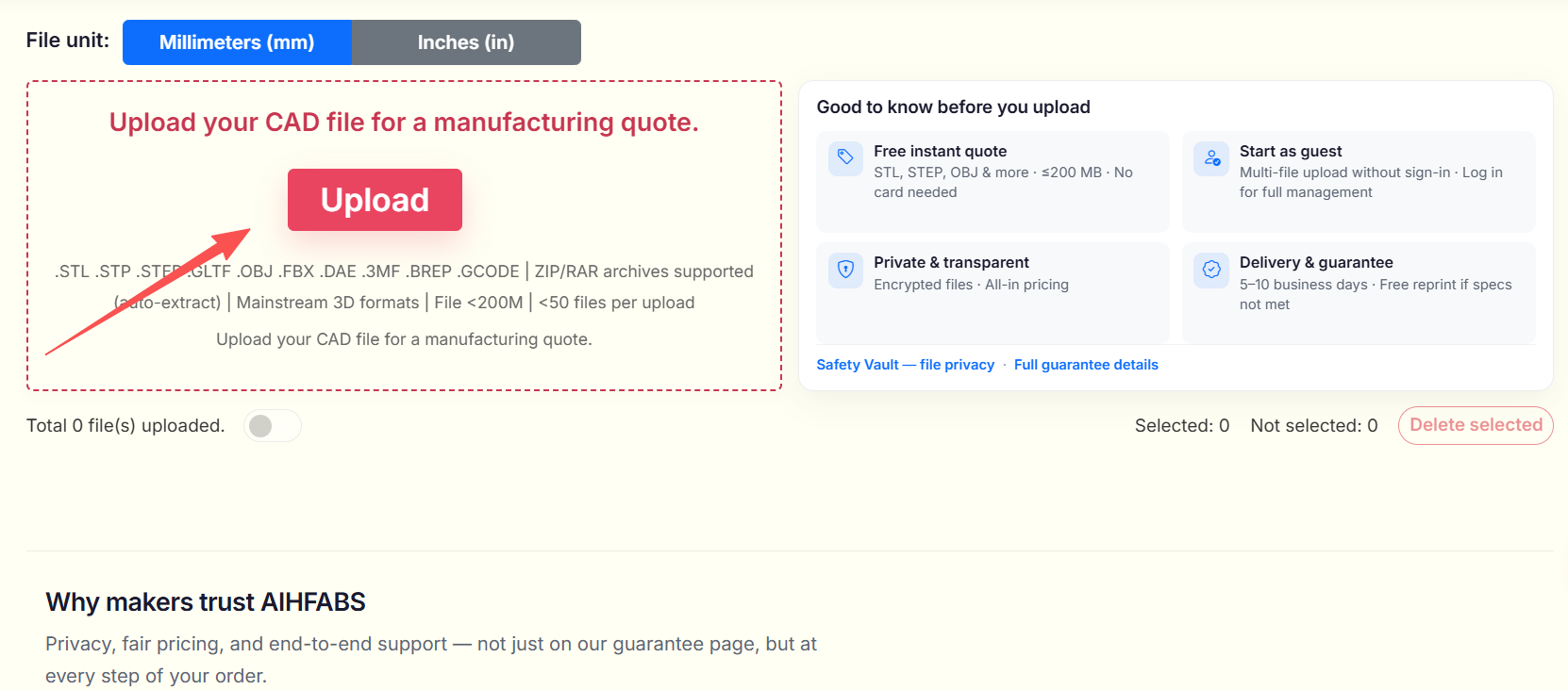
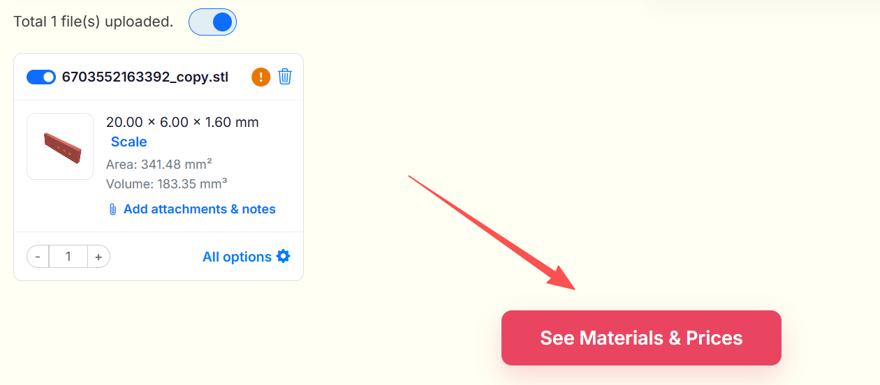
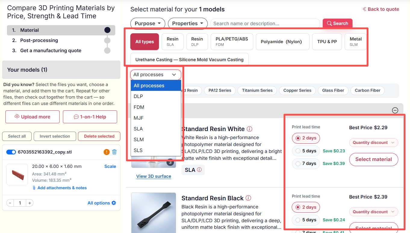
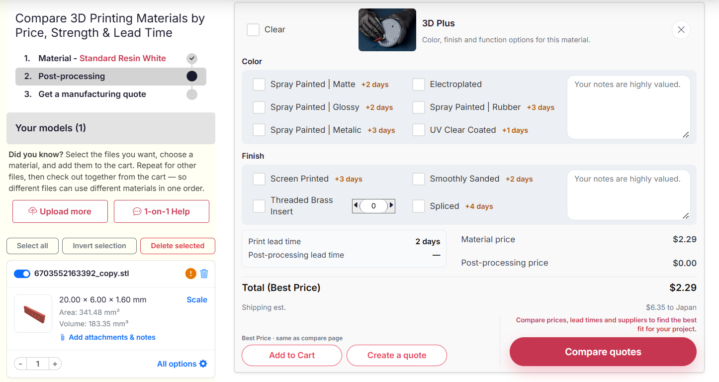
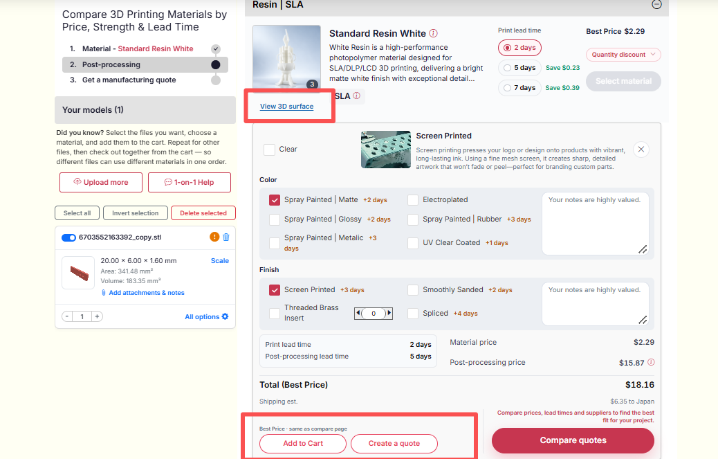
The animation illustrates the platform workflow. Available processes, finishes and lead times depend on the selected material.
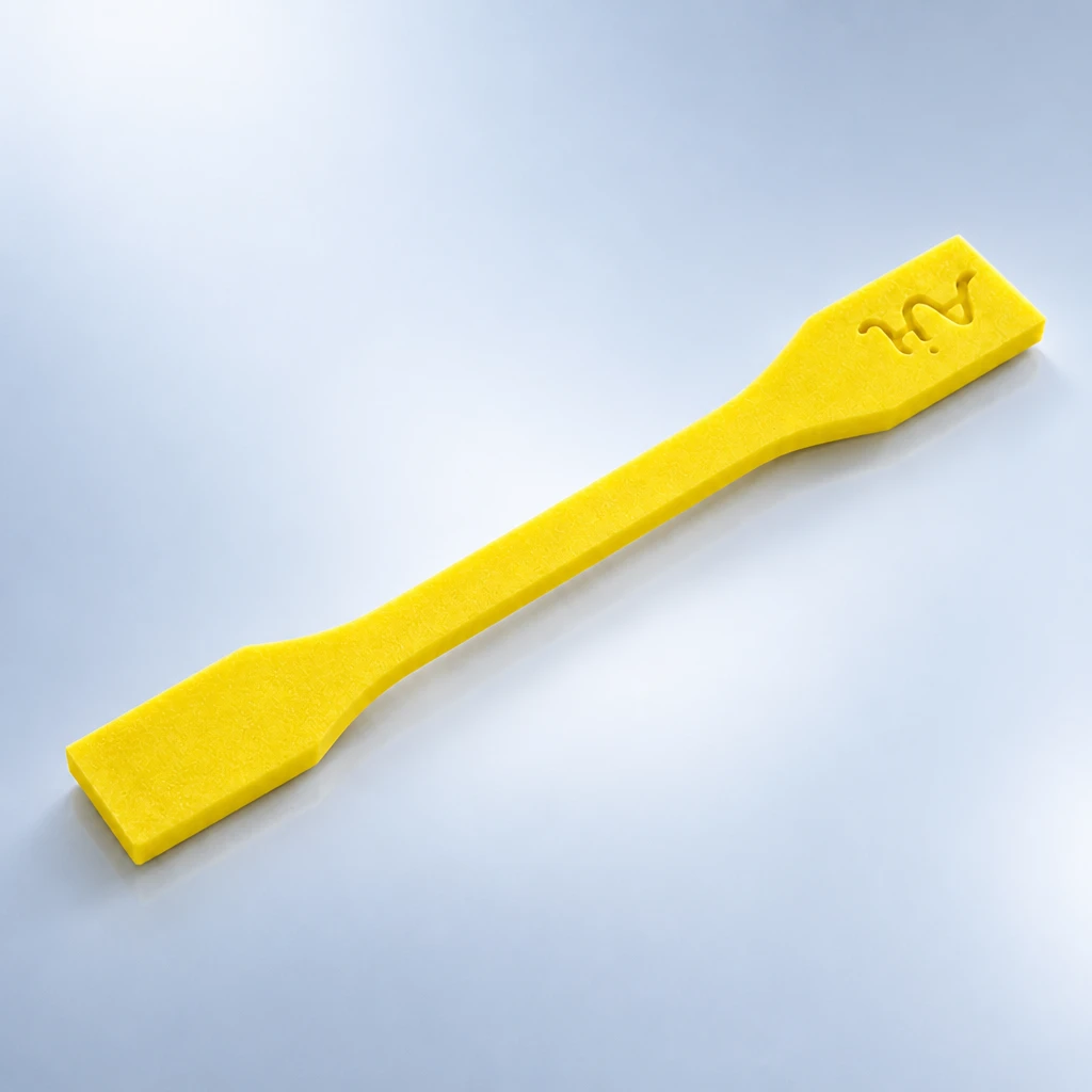
Stereolithography (SLA) cures liquid photopolymer with a precision UV laser, building parts layer by layer.
查看完整製程說明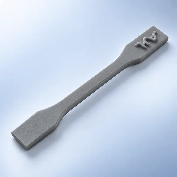
Digital Light Processing (DLP) solidifies an entire layer of photopolymer at once using a projected image.
查看完整製程說明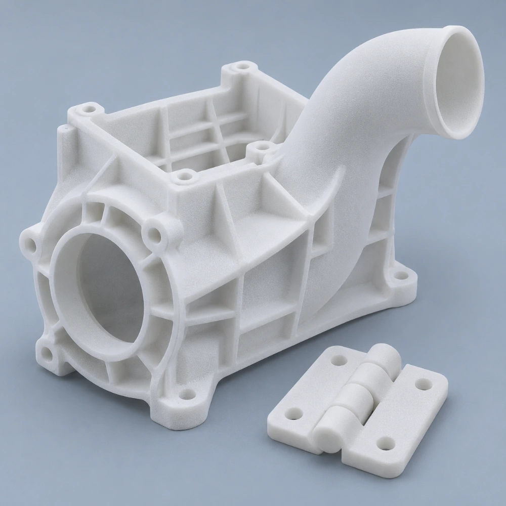
AIHFABS SLS 3D printing services fuse engineering-grade SLS plastics into durable, self-supporting parts.
查看完整製程說明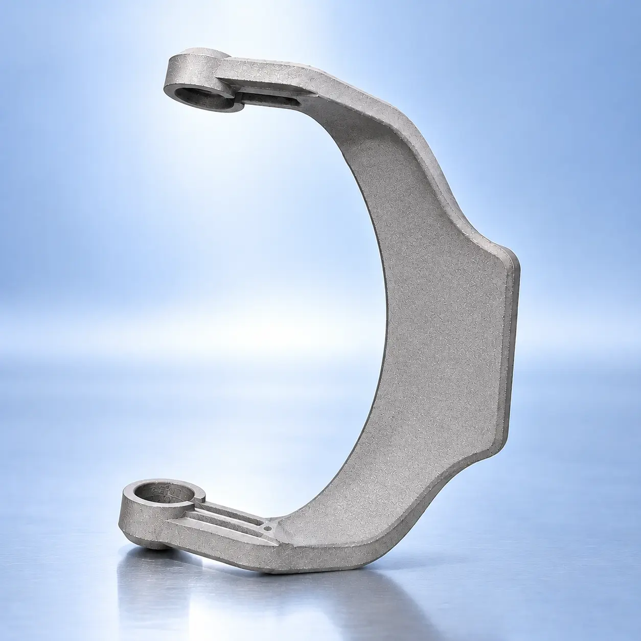
Multi Jet Fusion (MJF) applies fusing and detailing agents across a powder bed, then uses infrared energy to fuse each layer.
查看完整製程說明Early form-and-fit, large bulky geometry, and shop aids where layer lines are acceptable and cost matters.
About ±0.5 mm or ±0.5% on FDM-appropriate geometry. Fine fits belong on CNC or powder-bed nylon.
PLA, ABS, PETG, ASA, nylon, and carbon-filled blends. Tell us about heat, UV, and outdoors.
Yes — large-format cells are available. Envelope is confirmed after we open the file.
Many jobs leave in 24–48 hours depending on size and finish.
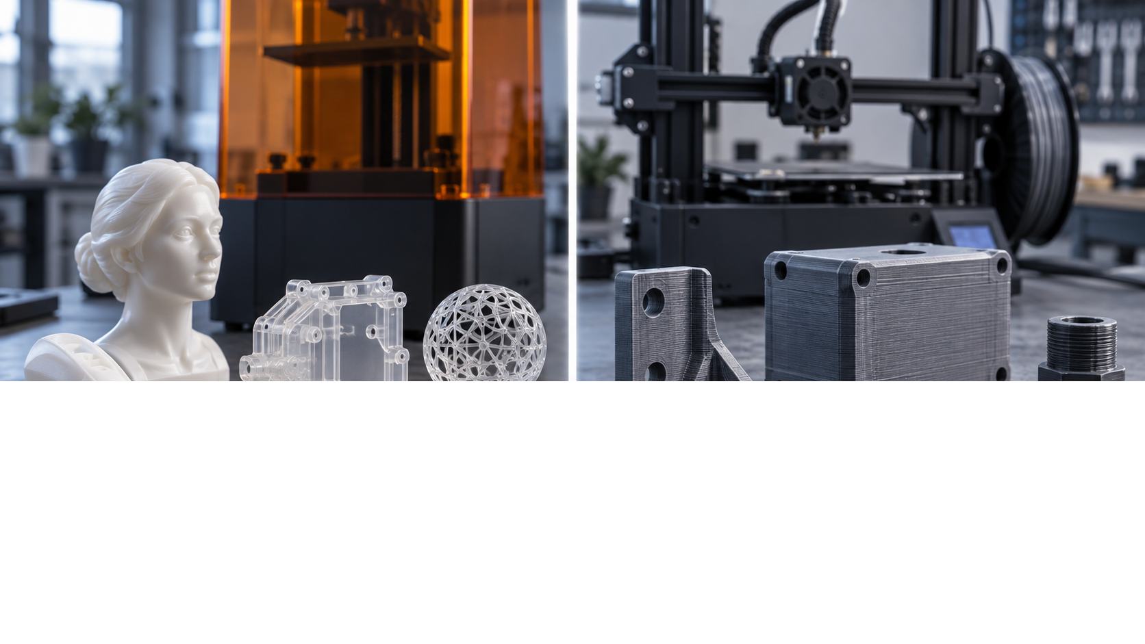
Compare SLA and FDM 3D printing for surface quality and fine details. Learn which technology suits smooth finishes, tight tolerances, and intricate geometries in prototyping and en
查看完整製程說明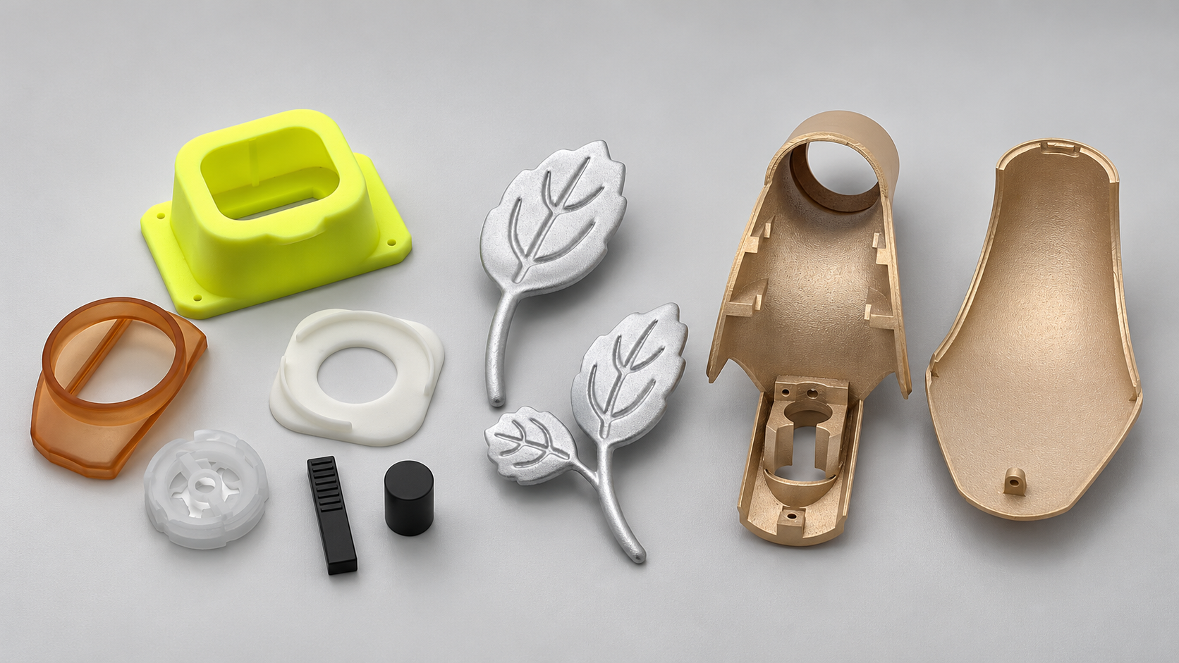
Compare SLA with DLP, LCD, FDM, SLS, MJF, SLM, and CNC machining. Shortlist processes by material, geometry, finish, cost, and your part's intended use.
查看完整製程說明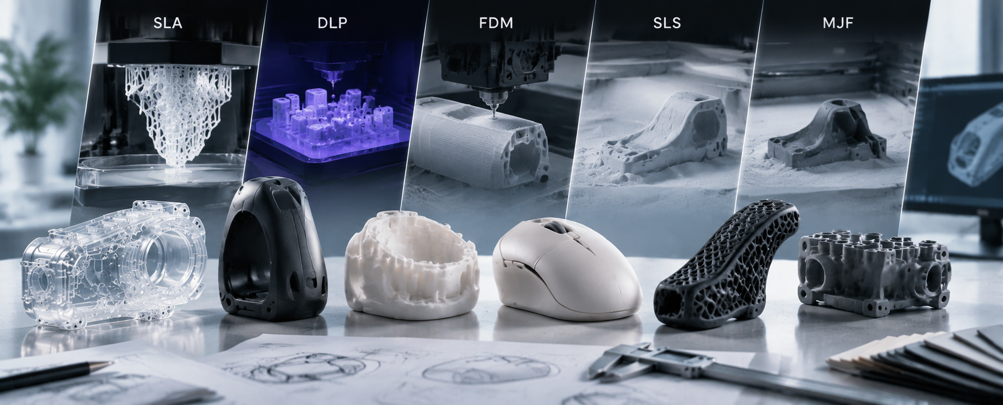
Learn how to choose the right 3D printing process for cosmetic prototype parts. Compare SLA, DLP, FDM, SLS, and MJF for surface quality, detail, fit, and finishing.
查看完整製程說明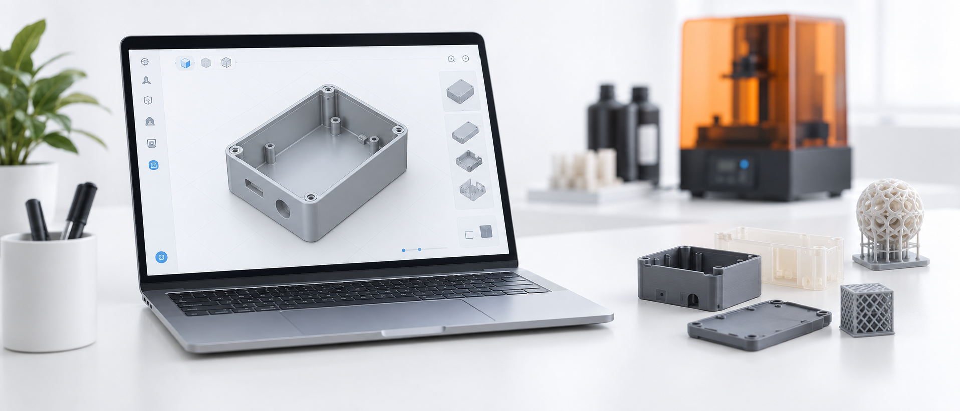
Step-by-step guide to uploading STL and STEP files for instant resin 3D printing quotes. Learn file preparation, unit settings, wall thickness, orientation, and how to read quote r
查看完整製程說明Use these process-specific checks when preparing your model, drawing and quote request. The confirmed quotation and approved drawing define the requirements for your part.
FDM parts are built from deposited roads and layers. Show the direction of load and the environment so orientation, wall strategy and material can be reviewed together. ABS and PETG are different materials; neither should be selected by appearance alone.
Support-facing surfaces can have a different texture and accuracy from accessible walls. Consider splitting a large part into an assembly when support removal is difficult. Specify inserts and threaded interfaces early, and state whether the part is a visual model or working fixture.
Confirm filament grade, build orientation where function depends on it, visible layer texture and required assembly fit. Discuss heat exposure and sustained load before using a printed fixture in production.
AIHFABS 根據 CAD 上傳為定制 3D 列印與 CNC 加工報價。比較 SLA、SLS、MJF、SLM、FDM、DLP、銑削與車削,並可在同一訂單中添加蒸汽拋光、染色、陽極氧化、拋光或粉末塗裝。
即時報價適合原型、治具、殼體與小批量。材料、工藝、數量與交期一起展示。
材料、工藝、數量與交期一起展示,減少工程變更後再發一輪供應商郵件。
上傳 STL、STEP 等常用 CAD 格式即可線上報價。
在同一零件上比較 3D 列印工藝與 CNC 選項。
選擇聚合物或金屬,需要時再添加 3D Plus 硬體後處理。
結算前查看價格與交期,特殊規格可申請人工報價。
若本頁描述的是你想再現的工藝、產業或樣品,請從上傳流程開始,把工藝與後處理與圖紙對齊。
選擇材料牌號與製造製程前,請先確認實際應用需求。

適用於支架及連接部件,具有較高比強度;用於飛行零件前,需審查疲勞、成形方向、熱處理與材料可追溯性。

適用於器械五金與夾具;選材時應考量腐蝕、滅菌循環與鈍化要求。

適用於輕量化外殼與研發支架;需評估振動、熱膨脹與螺紋連接的耐久性。

適用於夾爪與線纜導向件;需評估潛變、濕度影響與反覆彎曲。

適用於導熱與導電介面;需審查防氧化措施與接觸電阻。

適用於外殼原型;一般 ABS 本身不能證明具有靜電防護能力或特定阻燃等級。

適用於導電與導熱零件;需明確訂定接觸結構、鍍層與溫升驗收標準。

適用於絕緣夾具部件;需針對實際製程驗證釋氣、化學相容性與微粒產生情況。

適用於外觀原型與外殼;製模前需確認紋理、顏色與組裝效果。
我們使用 Cookie 優化瀏覽體驗。繼續使用即代表您同意我們的 隱私權政策
同意