

3D-Druck
Selektives Lasersintern (SLS)
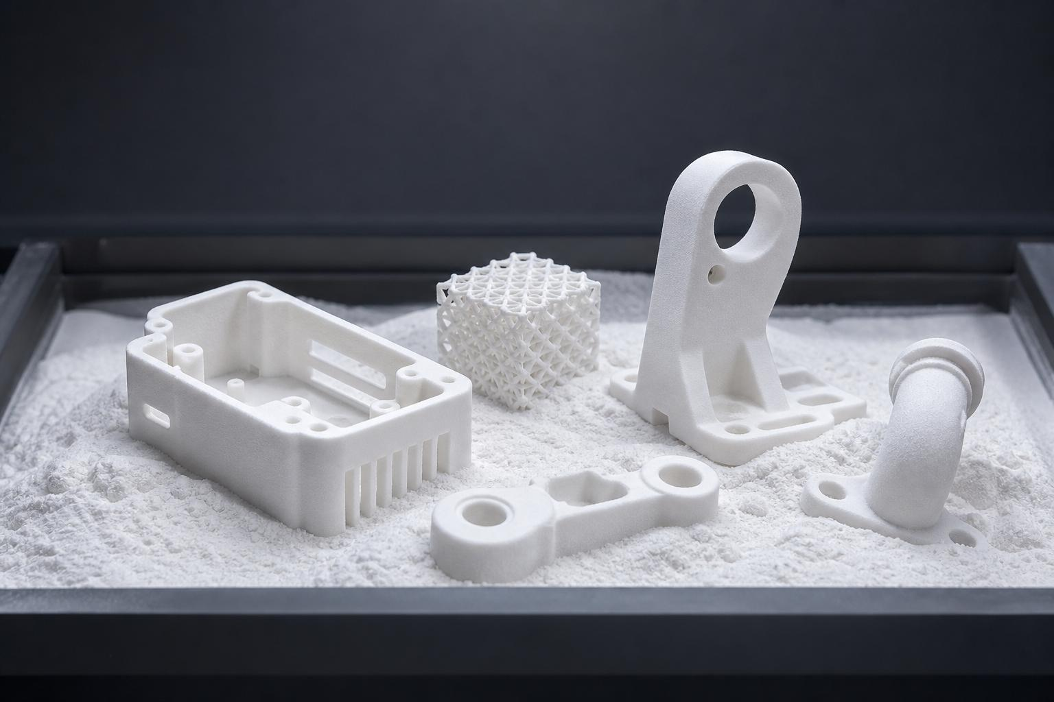
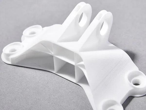
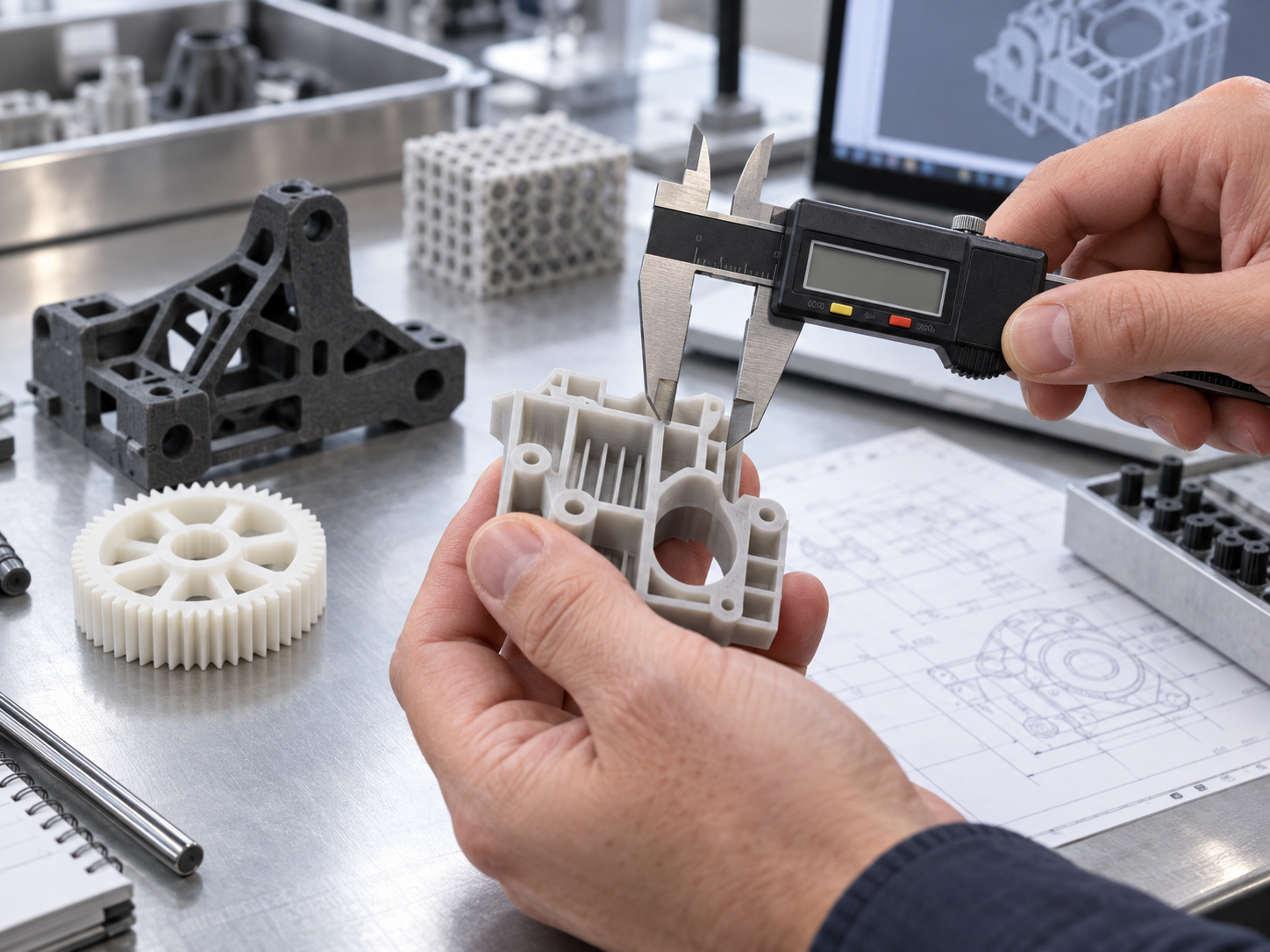
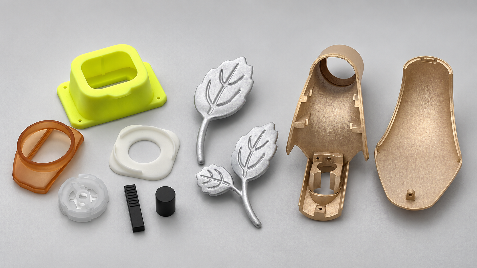
AIHFABS SLS 3D printing services fuse engineering-grade SLS plastics into durable, self-supporting parts.
Angebot erstellen
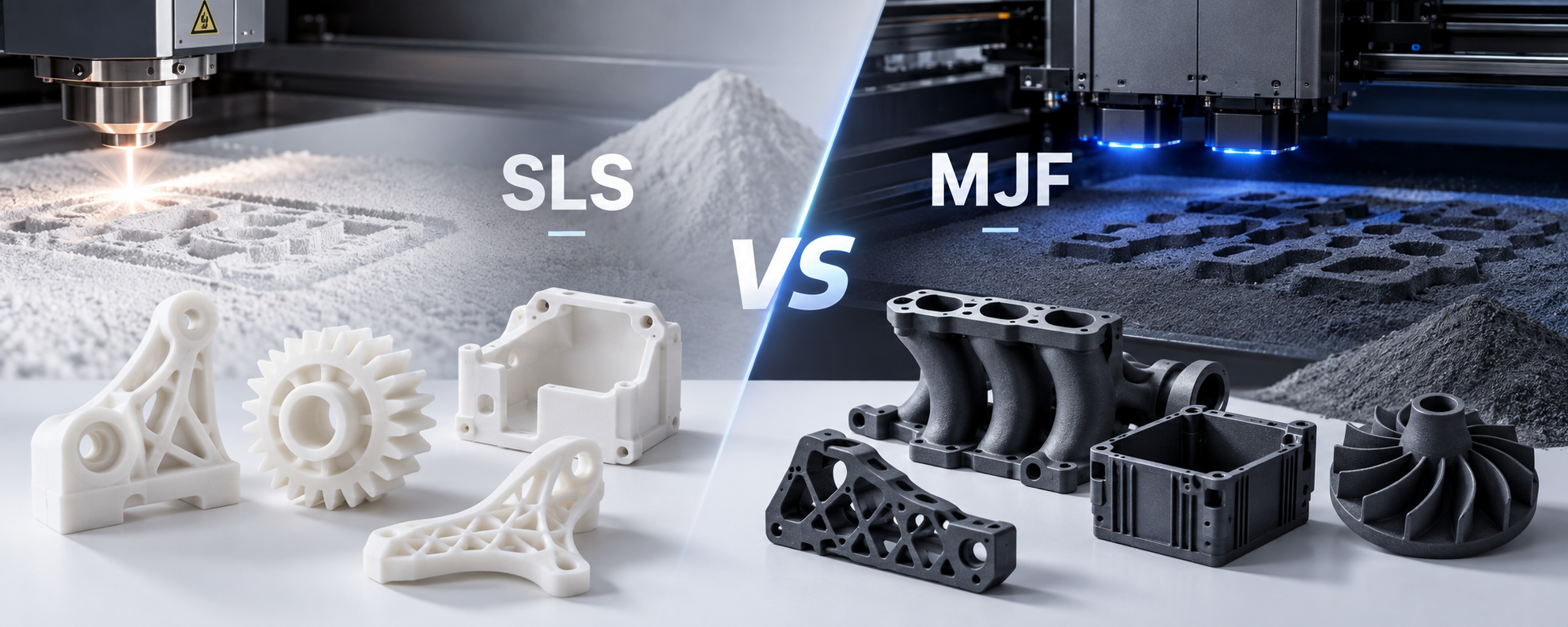
In modern manufacturing, industrial 3D printing has moved well beyond rapid prototyping into full-scale production of custom and short-run end-use functional parts. When it comes to production-grade nylon components, Selective Laser Sintering (SLS) and Multi Jet Fusion (MJF) stand out as the two most dominant Powder Bed Fusion (PBF) technologies in the industry.
While both processes produce durable, high-strength functional parts without the need for support structures, subtle differences in surface finish, dimensional consistency, production speed, and cost-efficiency can significantly impact your project's success. This guide provides a comprehensive side-by-side technical comparison of SLS and MJF to help engineers and procurement teams select the optimal nylon 3D printing service for their application.
Although SLS and MJF are both powder bed technologies that support toolless manufacturing and 3D nesting (printing parts freely without support structures), their underlying thermal fusion mechanisms differ fundamentally:
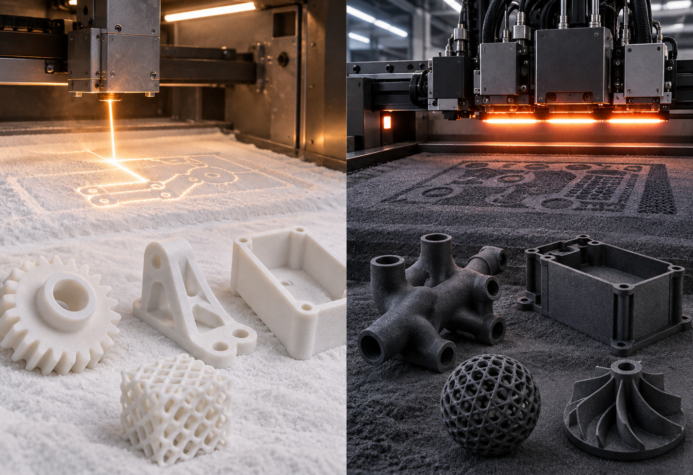
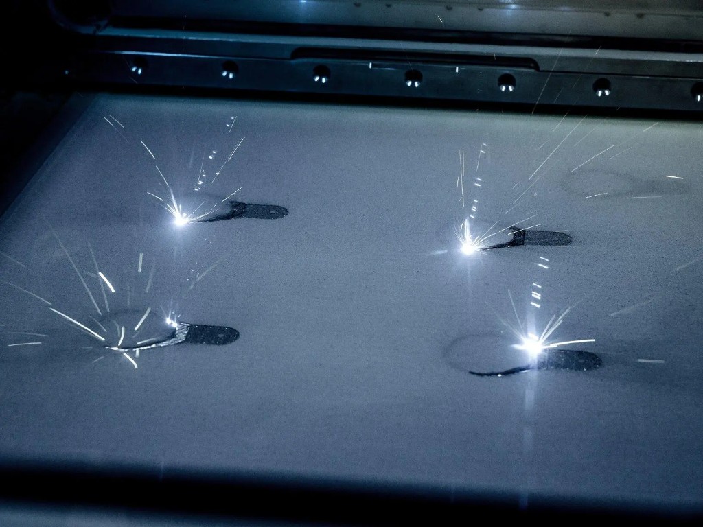
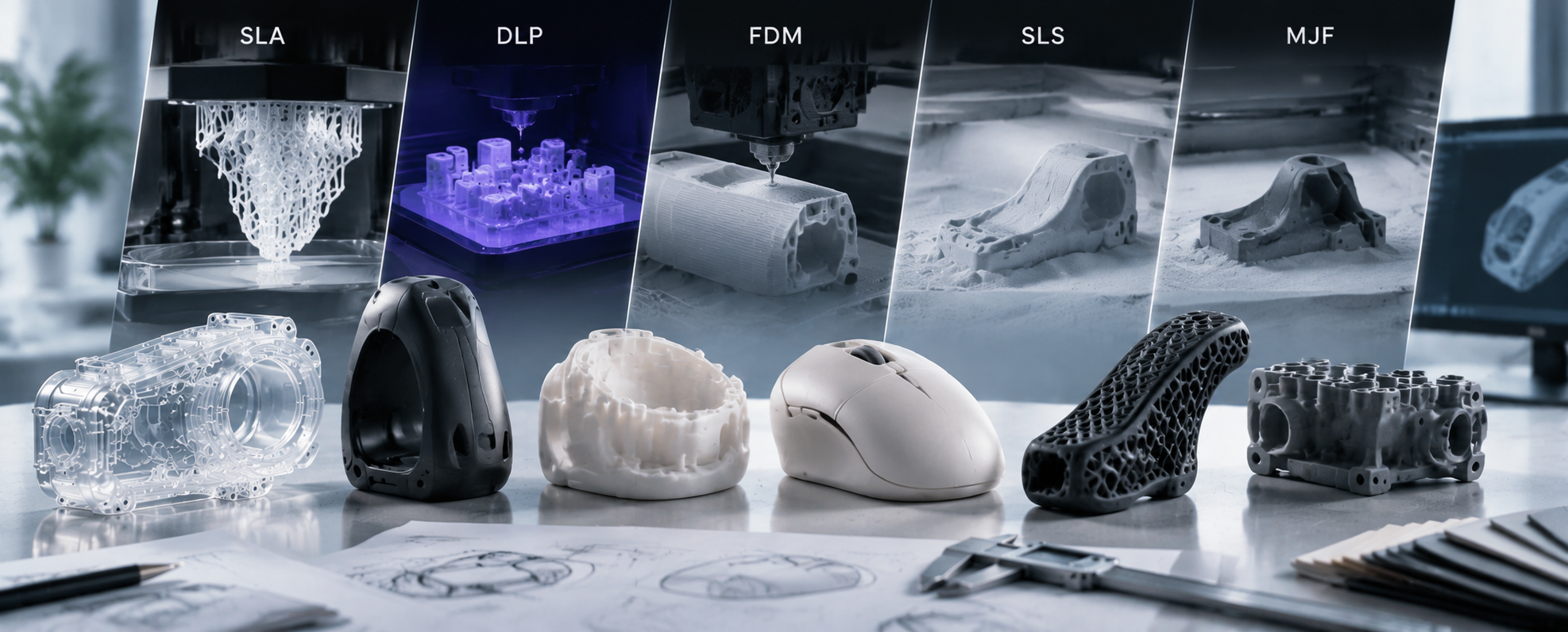
Selective Laser Sintering (SLS): Utilizes a high-power CO₂ or fiber laser to trace the cross-section of a part point-by-point. The laser melts and sinters polymer powder layers sequentially inside a heated build chamber.
Multi Jet Fusion (MJF): Employs an inkjet array printing head that passes across the powder bed, depositing a Fusing Agent (to absorb heat) where the part is formed, and a Detailing Agent (to restrict melting) around the contours. A sweeping infrared light lamp then passes over the entire bed, fusing the area line-by-line in a single pass.
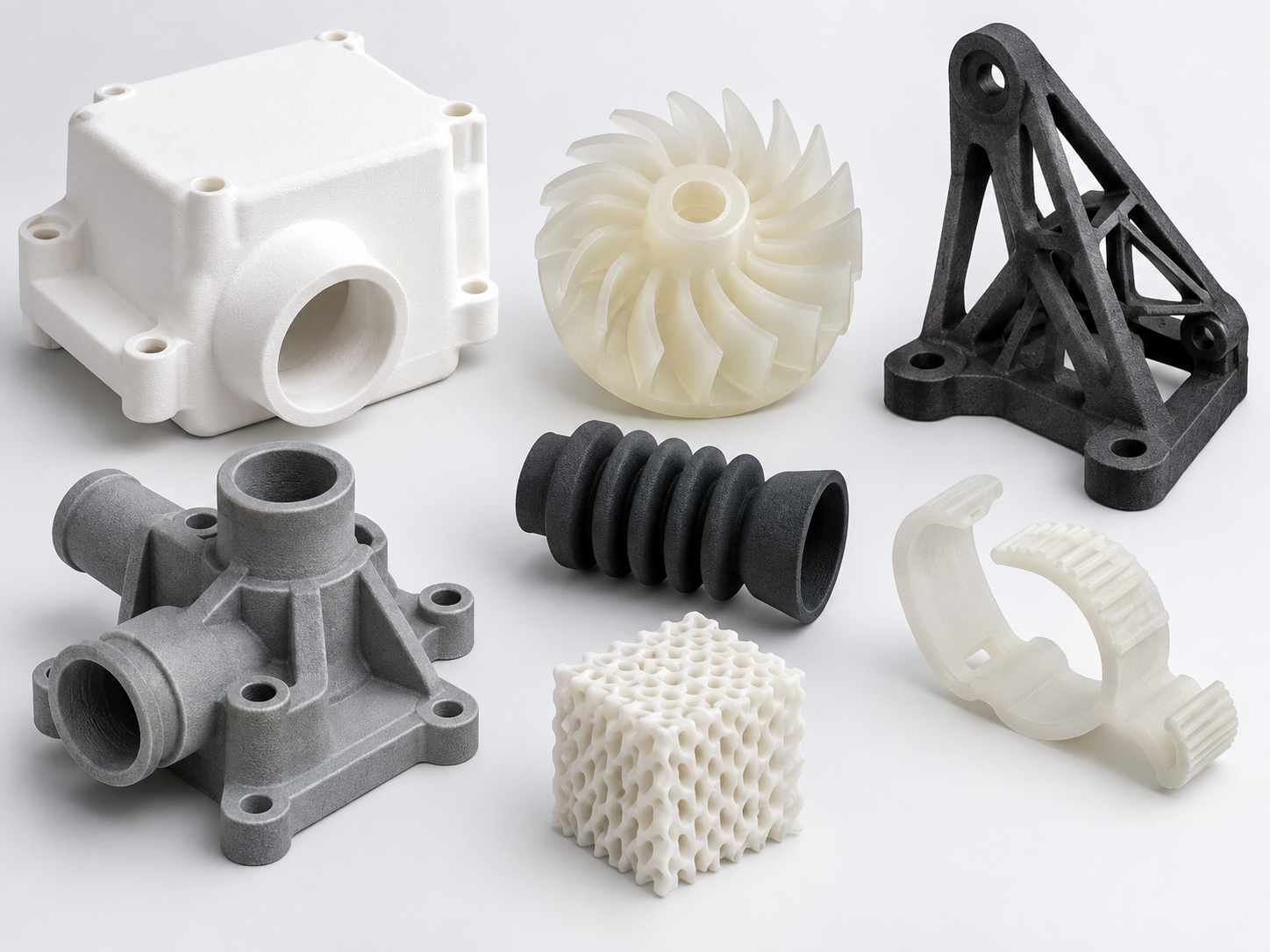
SLS: Offers a broader, more open-material ecosystem. Beyond standard PA12 and PA11, SLS extensively supports carbon-fiber-reinforced nylon, glass-filled nylon (PA12-GF), flame-retardant nylons, and flexible elastomers like TPU.
MJF: Features a tightly optimized material palette focused heavily on PA12, PA11, TPU, and PA12 Glass Beads. MJF materials are engineered to achieve exceptional density, low porosity, and highly uniform isotropic properties along all three axes (X, Y, Z).
 B. Dimensional Accuracy & Feature Resolution
MJF: Thanks to the precision detailing agent applied around boundaries, MJF achieves sharper edges, finer feature details, smaller minimum wall thicknesses (~0.8 mm), and tight dimensional tolerances (±0.2 mm).
SLS: Standard minimum wall thickness typically starts at 1.0 mm with a dimensional accuracy around ±0.3 mm. However, SLS manages thermal stress distribution exceptionally well on large, flat surfaces, minimizing localized warping.
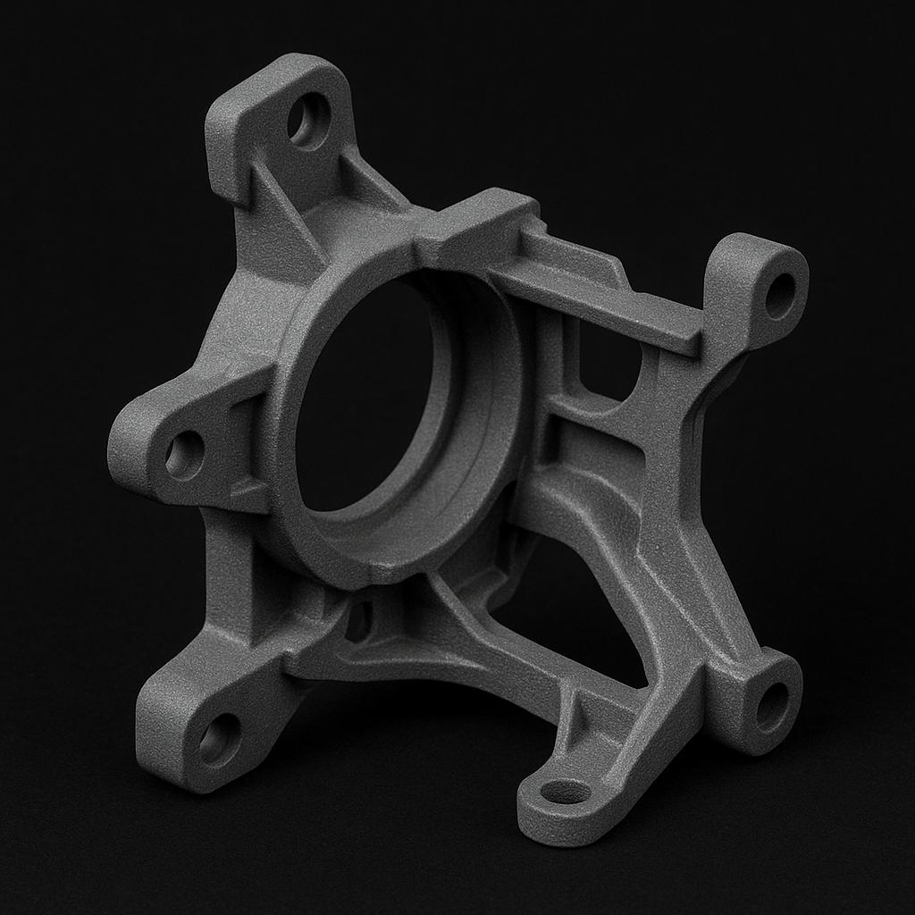
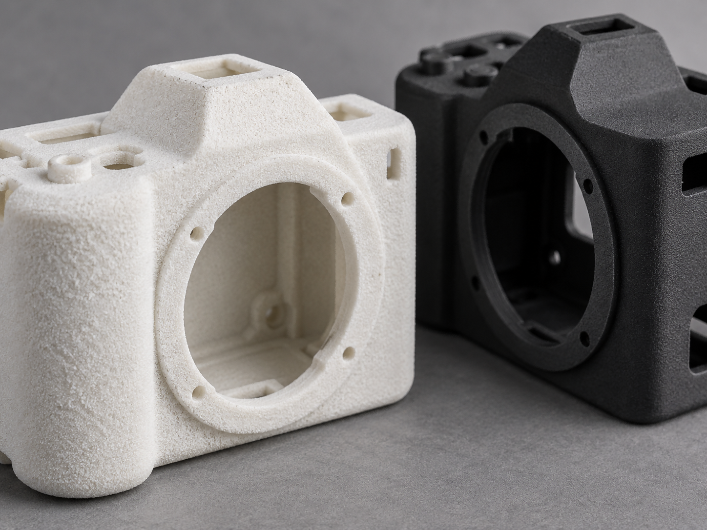
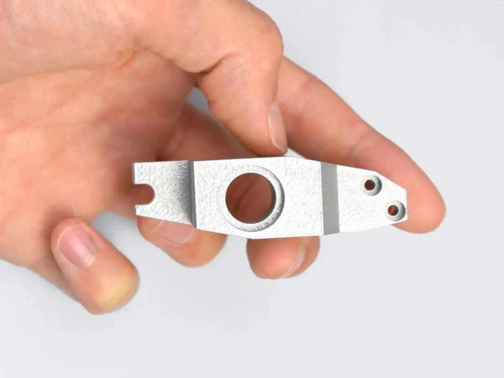
Raw Surface Texture: Raw SLS parts present a white or off-white uniform matte finish with a slight sugar-like granularity. Raw MJF parts feature a dark gray, fine speckled matte texture.
Dyeing & Post-Processing: For vibrant, custom color dyeing (red, blue, yellow, etc.), SLS's white base provides an ideal palette. For deep black or dark gray production finishes, MJF's natural dark tone accepts black dye perfectly for a uniform, premium look.
 D. Production Throughput & Cost Mechanics
MJF: Offers significantly faster area-based printing speeds. For high-density nested builds and mid-to-high batch production runs (10 to 1,000+ units), MJF delivers superior turnaround times (typically 3–5 days) and lower per-unit costs. Furthermore, MJF uses a fresh-to-recycled powder mix ratio of approximately 20/80, greatly reducing raw material waste.
SLS: Offers flexible turnaround for low-volume production (1 to 100 units) with typical lead times of 3–7 days, making it ideal for specialized geometries or single-part prototype runs.
Note: Specifications are based on general production standards and may vary depending on part geometry, orientation, and post-processing treatments.
Follow this step-by-step logic to determine whether SLS or MJF best fits your project parameters:
Step 1: Evaluate Material Requirements
——Need specialized composites (Carbon-filled, Flame-retardant, PA12-GF)? ──> Choose SLS
—— Using standard PA12, PA11, or TPU? ──────Proceed to Step 2
Step 2: Define Core Performance Metrics
—— Require maximum Z-axis strength, air/watertightness, or crisp micro-details? ─> Choose MJF
——Require large-format structural dimensions or custom color dyeing? ─────Choose SLS
Step 3: Assess Volume & Lead Time Constraints
——Prototype or low-volume run (1–10 parts)? ─────Choose SLS
—— Mid-to-large batch production (50–1,000+ parts) needing fast turnaround? ───── Choose MJF
Answer: Yes. Both technologies eliminate upfront tooling costs and operate without support structures, allowing high-density 3D nesting inside the build chamber. SLS is ideal for highly customized or lower-volume runs (1–100 parts), while MJF provides unparalleled scalability and unit-cost economics for runs between 10 and 1,000+ parts.
Answer: For very small quantities (1–5 units), SLS startup costs are often lower. However, as order volumes increase into dozens or hundreds of parts, MJF's higher printing speeds and 80% powder recyclability drastically reduce per-part costs, making it significantly cheaper at scale.
Answer: MJF typically delivers shorter lead times (3–5 days versus 3–7 days for SLS) because its line-by-line sweeping infrared light process prints entire layers faster than point-by-point laser scanning, significantly shortening build cycles.
Answer: Raw SLS parts have a powdery, slightly grainy white finish, whereas raw MJF parts have a smoother, dark gray matte texture. Both technologies can undergo secondary post-processing—such as media blasting, bead blasting, or vapor smoothing—to achieve injection-molded-quality surfaces.

Ein Verfahren zu diesem Artikel. Spezifikation öffnen oder die Datei auf ein Angebot legen.
AIHFABS SLS 3D printing services fuse engineering-grade SLS plastics into durable, self-supporting parts.
Angebot erstellen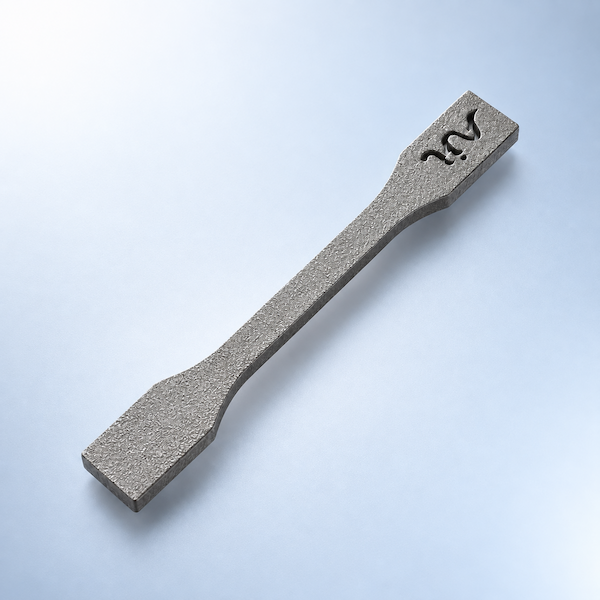
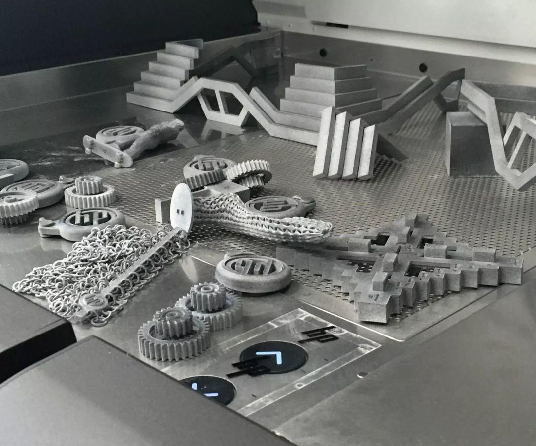
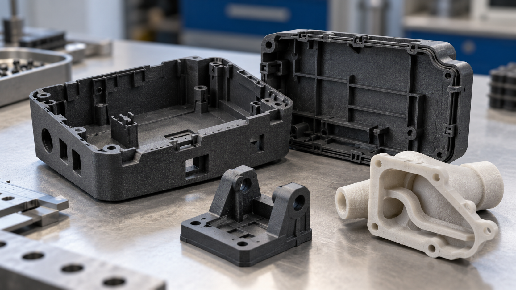
Multi Jet Fusion (MJF) applies fusing and detailing agents across a powder bed, then uses infrared energy to fuse each layer.
Angebot erstellenMaterialien neben diesem Artikel. Karte prüfen, dann CAD hochladen.
Notizen zu Verfahren, Finish und Dateien aus der Werkstatt.
Antworten zu Unternehmen, Zahlung, Versand und Verfahren nach Thema.
Questions about 3D printing processes, materials, MOQ, samples, and custom projects.
Production lead times, shipping options, and order tracking.
AIHFABS kalkuliert kundenspezifischen 3D-Druck und CNC aus einem CAD-Upload. Vergleichen Sie SLA, SLS, MJF, SLM, FDM, DLP, Fräsen und Drehen und fügen Sie Dampfglätten, Färben, Eloxieren, Polieren oder Pulverbeschichten derselben Bestellung hinzu.
Sofortangebote eignen sich für Prototypen, Vorrichtungen, Gehäuse und Kleinserien. Werkstoff, Verfahren, Menge und Lieferzeit stehen zusammen.
Werkstoff, Verfahren, Menge und Lieferzeit stehen zusammen, damit Konstruktionsänderungen keine neue Lieferantenrunde auslösen.
STL, STEP und gängige CAD-Formate für ein Online-Angebot hochladen.
3D-Drucktechnologien und CNC am gleichen Teil vergleichen.
Polymere oder Metalle wählen und bei Bedarf 3D-Plus-Hardware-Finish hinzufügen.
Preis und Lieferzeit vor dem Checkout prüfen oder ein manuelles Angebot anfordern.
Beschreibt diese Seite ein Verfahren, eine Branche oder ein Musterteil, starten Sie mit dem Upload und stimmen Sie Technologie plus Finish auf Ihre Zeichnung ab.
Wir verwenden Cookies, um Ihre Erfahrung zu personalisieren. Mit der Nutzung stimmen Sie unserer Datenschutzrichtlinie
Akzeptieren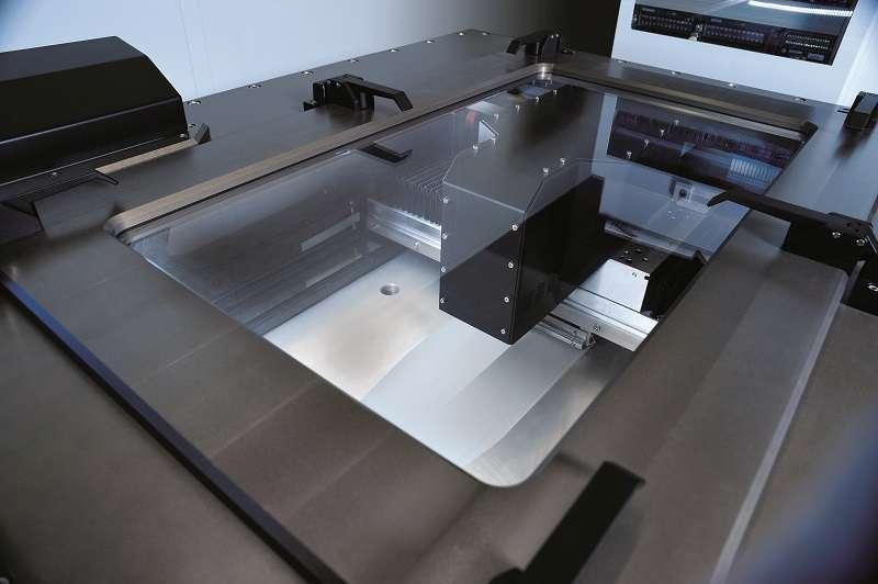

Kommentar hinterlassen