Lead time
From 5 business days (express options where available)

Impression 3D
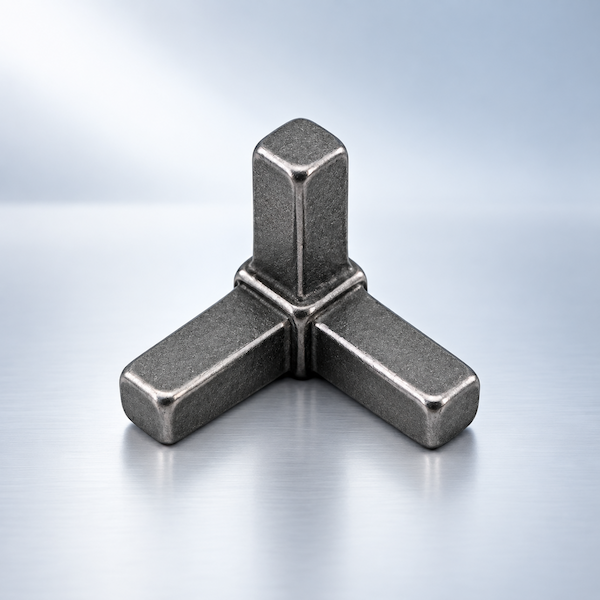
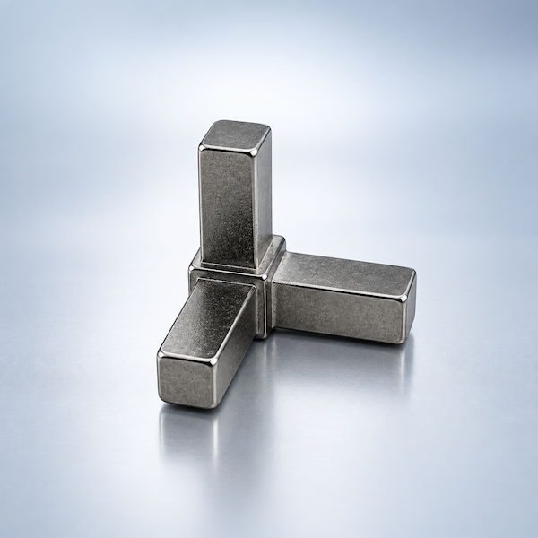
Fully dense metal parts built layer by layer from fine metal powder.
Selective Laser Melting (SLM) is a powder-bed metal additive process. A high-power laser scans each cross-section of your CAD model, melting metal powder that solidifies into a dense part. SLM is suited to lightweight structures, internal channels, and consolidated assemblies that are costly or impossible to machine from solid stock.
Impression 3D métal SLM pour pièces fonctionnelles complexes — Examinez la géométrie, les matières, l’enveloppe de fabrication, les finitions et les informations nécessaires à un devis utile.
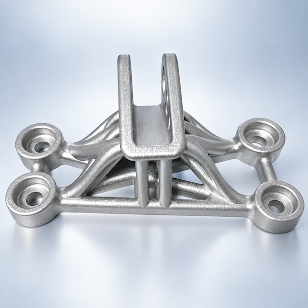
Selective Laser Melting builds a metal part from powder. A recoater spreads a thin layer; a laser melts the slice; the plate drops and the cycle repeats. The solid that comes off the plate is near-full density, which is why SLM is used for brackets, cooling inserts, and parts that would waste a lot of billet on a mill.
Supports, heat treat, and optional CNC on datums are part of the route, not extras you discover later. AIHFABS quotes SLM when the geometry — channels, lattices, or a consolidated assembly — is the reason to print instead of machine from stock.
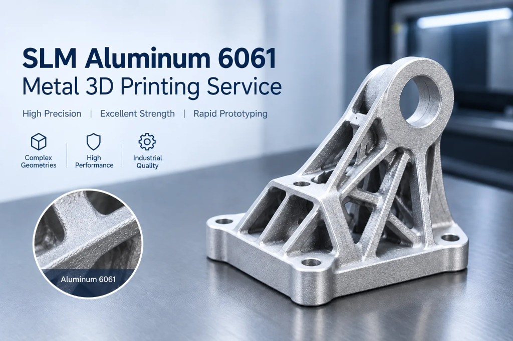
Envelope and as-built tolerance are planning values. Threads and bearing seats are usually finished on a mill.
From 5 business days (express options where available)
±0.3 mm or ±0.3% (whichever is greater), tighter after machining
420 × 420 × 450 mm (larger projects — contact us)
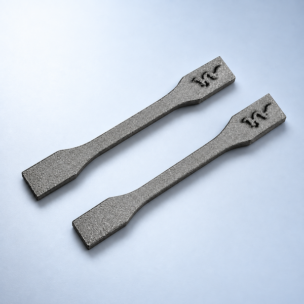
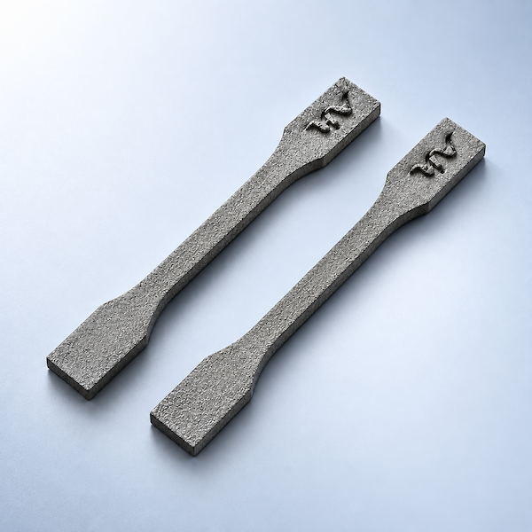
As-built grainy metallic; polishing, coating, or CNC finishing available
Required for overhangs; removed in post-processing
Aluminum, titanium, and stainless powders are the everyday set. Tool steel and nickel alloys are reviewed per job.
As-built metal is grainy. Plan a secondary operation on any face that seals, bears, or faces a customer.
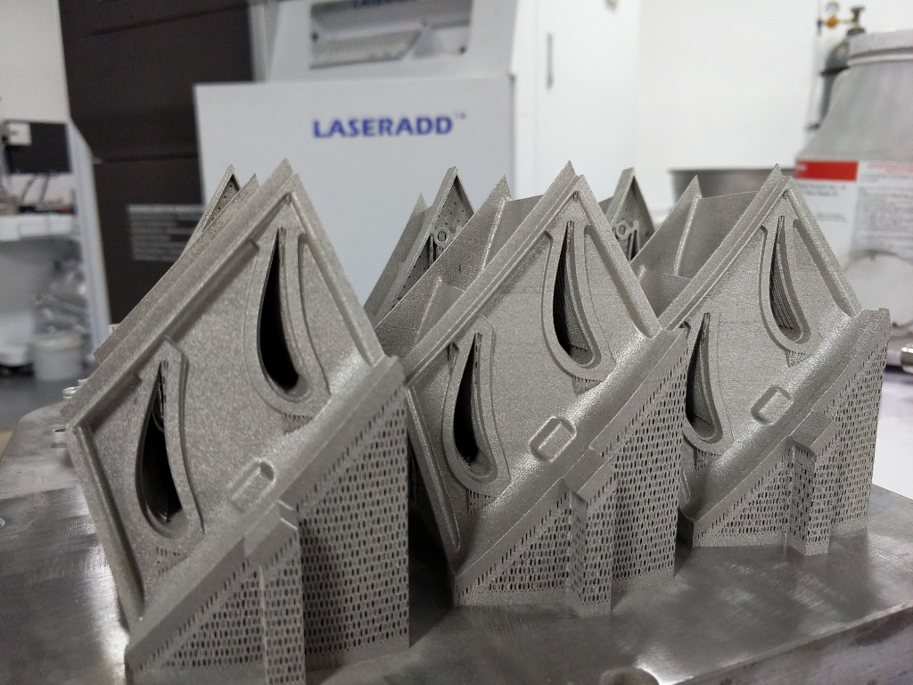
Grainy metallic skin from the powder bed. Fine for hidden structures and many brackets after support removal.
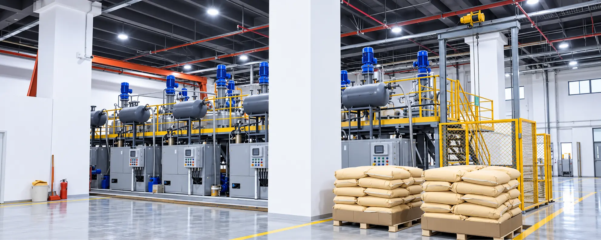
Stress relief or HIP-class heat treat as specified, then powder removed from channels and lattices.
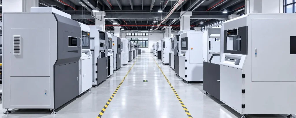
Mill or turn datums, threads, and sealing faces; polish or coat show surfaces.
SLM is the metal powder-bed option. Nylon jobs belong on SLS or MJF; resin detail belongs on SLA, DLP, or LCD.
| Procede | Delai | Tolerance | Tarif |
|---|---|---|---|
| Fusion laser sélective (SLM)Metal | From 5 business days (express options where available) | ±0.3 mm or ±0.3% (whichever is greater), tighter after machining | Instant quote · typical metal part from $90 |
| Stéréolithographie (SLA)Resin | Quoted with your CAD upload | Instant quote · typical resin part from $18 | |
| Traitement de la lumière numérique (DLP)Resin | From 48 hours | ±0.2 mm on supported geometry | Instant quote · typical resin batch from $20 |
| Affichage à cristaux liquides (LCD)Resin | From 48 hours | ±0.2 mm on supported geometry | Instant quote · typical resin part from $16 |
| Frittage laser sélectif (SLS)Plastic powder | From 48 hours express; 72 hours / 5 days standard tiers | ±0.3 mm or ±0.3% | Instant quote · typical nylon part from $28 |
| Multi Jet Fusion (MJF)Plastic powder | From 48 hours express; standard 72 hours / 5 days | ±0.3 mm or ±0.3% | Instant quote · typical PA12 part from $25 |
| Modélisation par dépôt de fusion (FDM)Thermoplastic filament | From 24–48 hours depending on size | ±0.5 mm or ±0.5% on FDM-appropriate geometry | Instant quote · typical prototype from $12 |
Your 3D model is oriented, supported where needed, and sliced into thin layers.
A recoater spreads a uniform layer of metal powder across the build plate.
The laser melts the powder along the slice contour; the plate lowers and the cycle repeats.
After printing, parts are depowdered, supports removed, and finished with heat treat or machining as required.
Orientation, supports, and escape paths are checked before the build. Blind cavities without a powder exit are redesigned or rejected.
After the build, parts are depowdered, heat-treated as specified, then support-removed. Inspection follows the faces you marked for machining.
Design for powder, heat, and a finishing mill — not only for the laser path.
| Feature | Recommended practice |
|---|---|
| Overhangs | Self-supporting above about 45°. Steeper faces need supports, fillets, or a lattice blend. |
| Channels | Give powder an exit on every blind cavity and narrow duct. |
| Fits & threads | Call out secondary machining on critical diameters and threads. |
| Walls | Avoid paper-thin unsupported skins; they warp in the furnace and on the plate. |
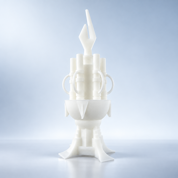
Stereolithography (SLA) cures liquid photopolymer with a precision UV laser, building parts layer by layer.
Fiche procede
Digital Light Processing (DLP) solidifies an entire layer of photopolymer at once using a projected image.
Fiche procede
Liquid Crystal Display (LCD) printing — also called MSLA — cures a full layer of photopolymer at once.
Fiche procedeWhen internal channels, lattices, or a single printed assembly beat a stack of milled pieces — prototypes, spares, and small functional batches.
Aluminum AlSi10Mg and 6061, titanium Ti6Al4V, stainless 316L and 17-4 PH. Tool steel and nickel alloys are reviewed by project.
Listed envelope is 420 × 420 × 450 mm. Typical as-built tolerance is ±0.3 mm or ±0.3%, whichever is greater. Tighter fits are machined.
A grainy metallic skin. We polish, coat, or CNC faces that need a smoother or more accurate interface.
STEP or STL, alloy, quantity, critical dimensions, environment, finish, and ship-to. Instant quote first, then a build-route review.
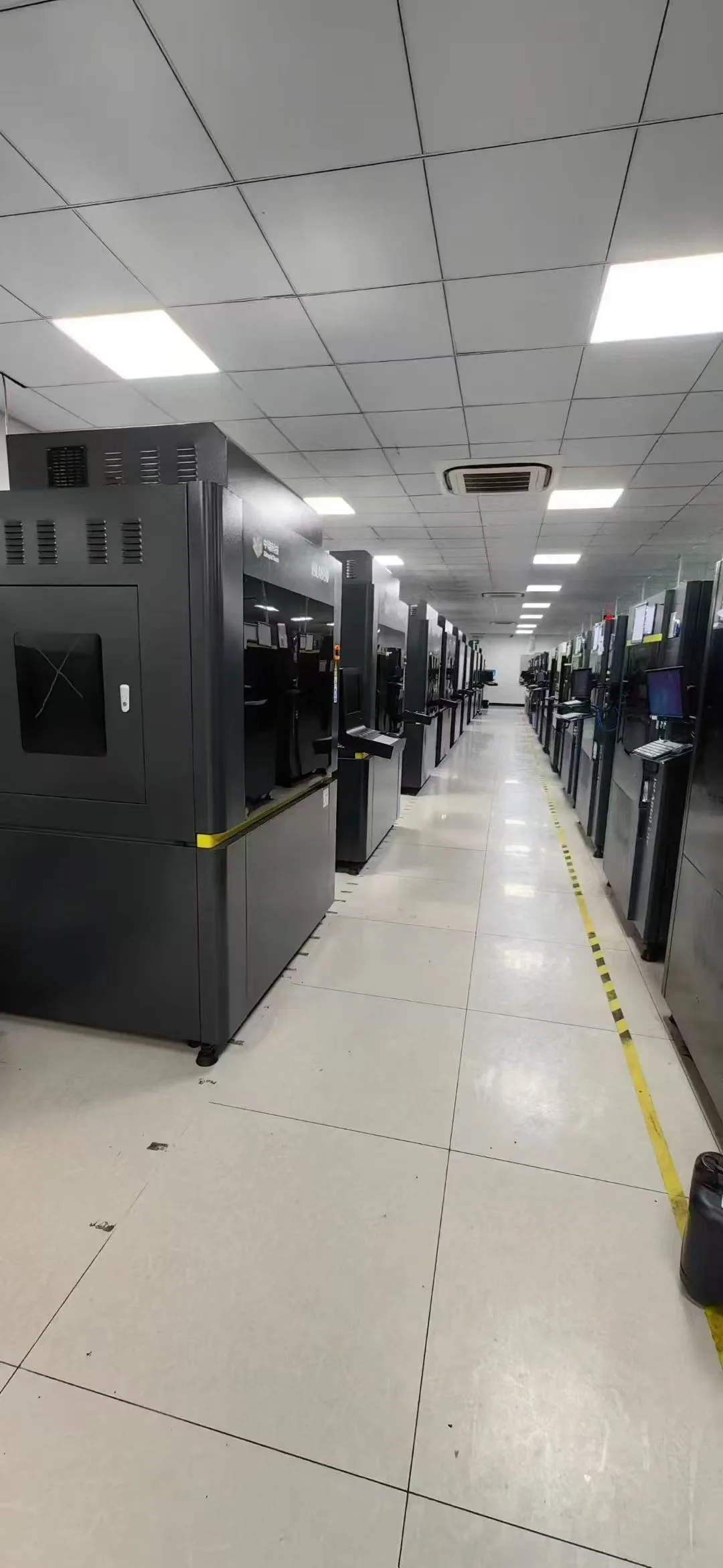
In the world of advanced manufacturing, Metal 3D Printing is revolutionizing how we build everything from aerospace components to medical implants. But the journey from a digital f
Fiche procede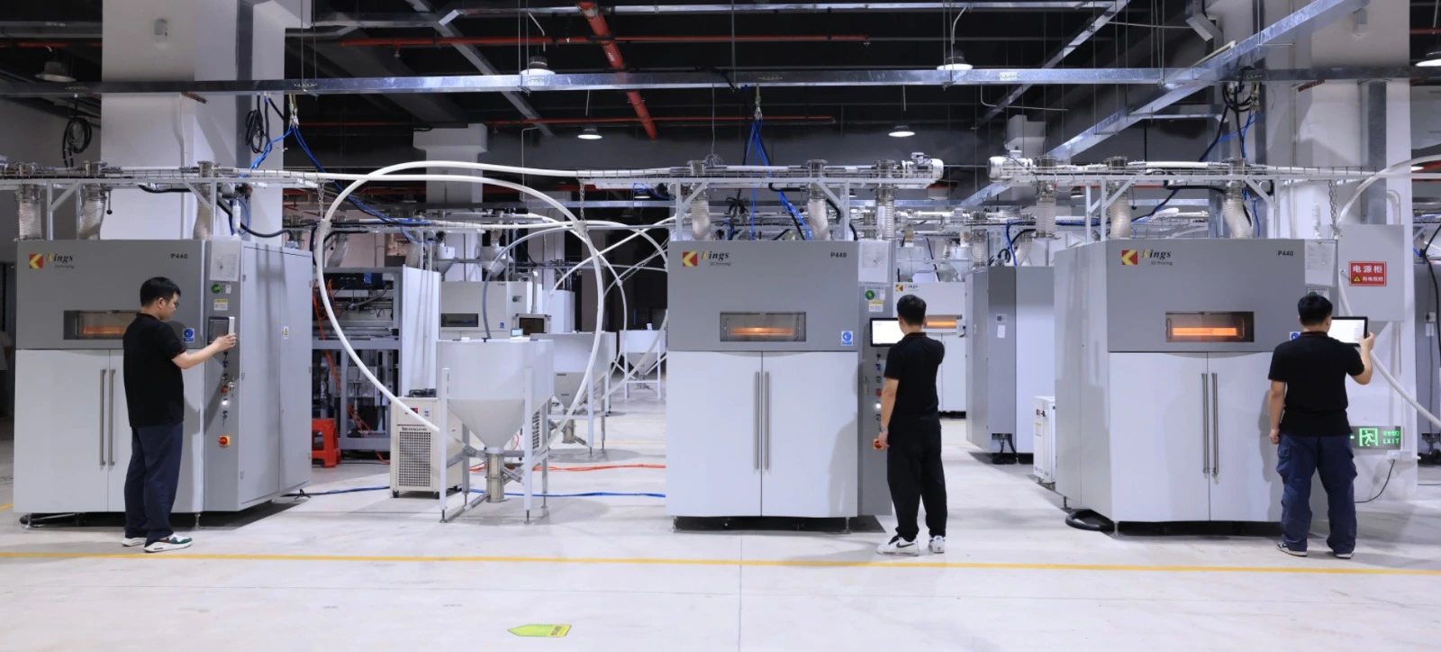
For low-volume metal parts, choosing SLM vs CNC is a system decision. SLM excels in complex geometry like internal channels and part consolidation. CNC suits simpler shapes and fin
Fiche procede
SLM parts are used in aerospace, auto, medical, and robotics. Industry names signal context, not certification. SLM fits complex, light parts. Final use needs process control and v
Fiche procede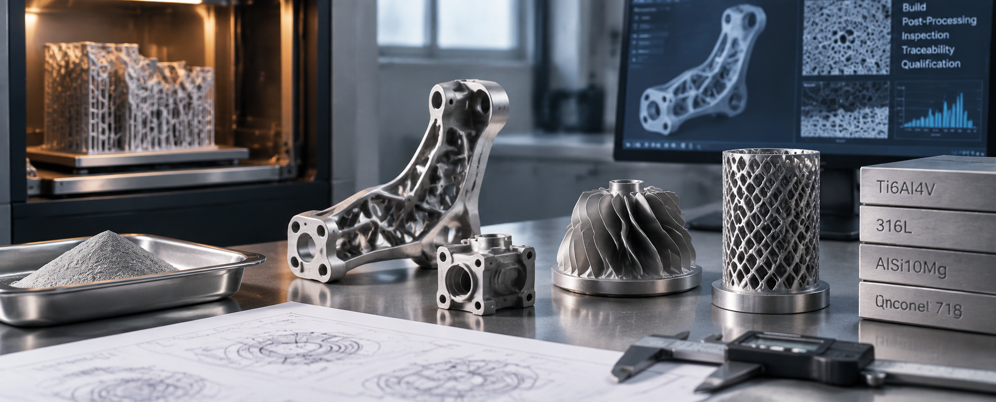
Evaluate SLM suppliers with an evidence-based checklist covering material traceability, process capability, post-processing, inspection, and procurement decisions for functional me
Fiche procede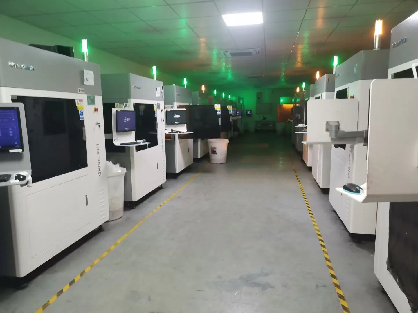
Qualifying SLM suppliers for functional metal parts requires an evidence-based approach. This guide outlines three critical Evidence Gates to ensure reliability. First, verify Mate
Fiche procede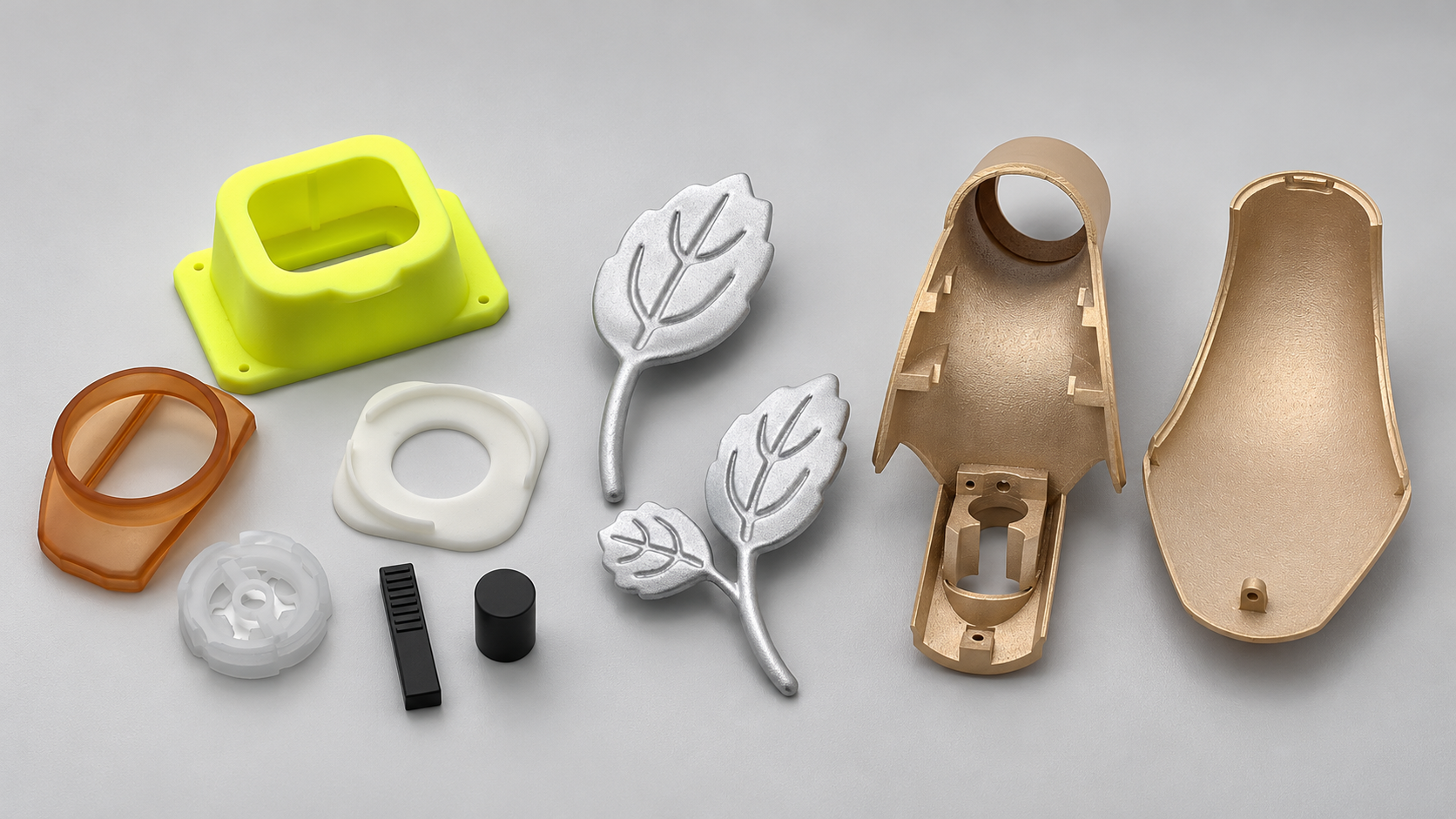
Compare SLA with DLP, LCD, FDM, SLS, MJF, SLM, and CNC machining. Shortlist processes by material, geometry, finish, cost, and your part's intended use.
Fiche procedeUse these process-specific checks when preparing your model, drawing and quote request. The confirmed quotation and approved drawing define the requirements for your part.
Use SLM where geometry adds functional value: internal flow paths, load-directed lightweight structures, lattices or the consolidation of several assembled parts. Straightforward stock shapes and easily accessible features may be better machined. Compare the complete route, including supports, cleaning, thermal processing and final machining, rather than the print operation alone.
For a lightweight bracket, identify the load path and preserve the mounting interfaces. For an internal passage, define powder-removal access, inspection access and any leak-test requirement together. For a consolidated assembly, identify the joints being eliminated and retain the interfaces that require machining. Validate fit and function on a first article before repeat production.
Metal supports anchor the build and help manage heat. They must be accessible for removal. Internal passages also need an effective powder-evacuation route. Identify overhangs, closed cavities and internal surfaces that cannot be reached after printing.
Residual stress and removal from the build plate can affect dimensions. Discuss heat treatment, support removal sequence and secondary machining before the build. Leave agreed machining stock on bearing seats, threads, sealing faces and datum features where required.
Confirm alloy, thermal condition, machined surfaces, surface texture and inspection requirements. Density, leak testing, material documentation or other special checks must be requested and agreed for the specific order.
AIHFABS chiffre impression 3D et usinage CNC à partir d’un upload CAO. Comparez SLA, SLS, MJF, SLM, FDM, DLP, fraisage et tournage, puis ajoutez lissage vapeur, teinture, anodisation, polissage ou thermolaquage à la même commande.
Le devis instantané convient aux prototypes, gabarits, boîtiers et petites séries. Matière, procédé, quantité et délai s’affichent ensemble.
Matière, procédé, quantité et délai s’affichent ensemble, pour éviter un nouveau tour de mails fournisseurs à chaque modification.
Téléversez STL, STEP et formats CAO courants pour un devis en ligne.
Comparez technologies d’impression 3D et options CNC sur la même pièce.
Choisissez polymères ou métaux, puis ajoutez une finition hardware 3D Plus si besoin.
Vérifiez prix et délai avant paiement, ou demandez un devis manuel.
Si cette page décrit un procédé, un secteur ou une pièce à reproduire, partez de l’upload et alignez technologie et finition sur votre plan.

Nous utilisons des cookies pour personnaliser votre expérience. En utilisant ce site, vous acceptez notre Politique de confidentialité
Accepter