Design details: Metal Intake Manifold — DMLS Prototype
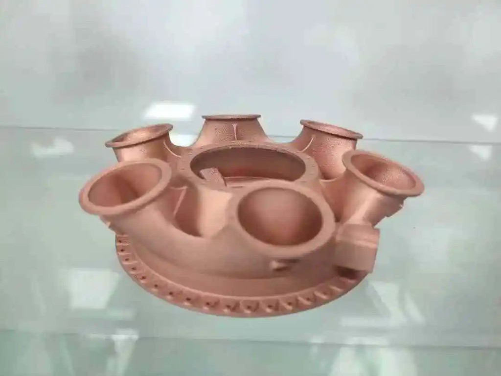
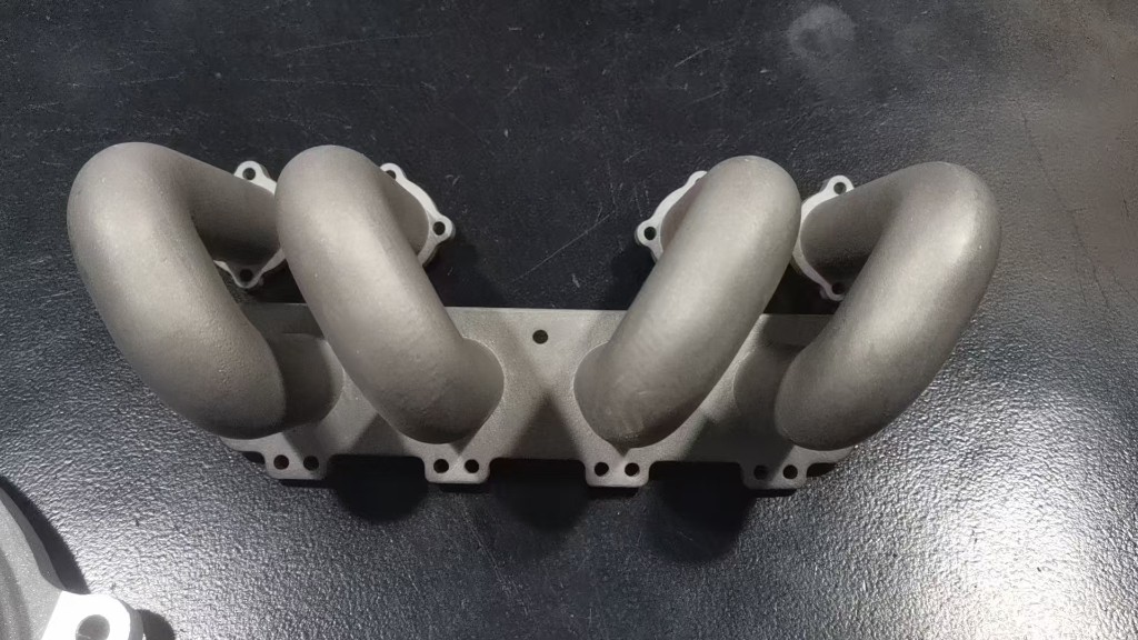
Four curved tubular runners sit above a shared elongated flange. Circular holes in the flange and smaller mounting tabs surround the visible connection points. The silver-grey surface and close spacing of the runners make the outer geometry easy to compare, while the enclosed passage surfaces remain out of view.
For a similar manifold, separate the packaging review from the interface review. The runner curves must clear neighboring components, while bolt positions, port profiles and sealing faces must match the mating assembly. Use a sectioned CAD view to check internal routes and wall transitions; the photograph alone cannot show passage continuity or wall thickness.
Features to review on a similar design
- Plan powder evacuation from every internal passage
- Specify machining allowances for sealing faces
- Define leak and flow checks for the intended application
Metal additive manufacturing review
This entry is catalogued as a metal additive manufacturing prototype. For a similar four-runner manifold, review build orientation together with support access around the bends and mounting tabs. Each enclosed runner needs a practical powder-removal route, followed by any required stress relief and interface machining. Specify the alloy, service temperature and pressure requirements before selecting a production route. Neither a DMLS label nor the photographed surface establishes the alloy grade, dimensional accuracy or suitability for engine operation.
Explore process capabilities and material optionsSandblasting considerations
Sandblasting is the finish listed for this sample. For a similar manifold, define which external surfaces should have a uniform matte texture and which sealing faces, threads or locating bores need protection or later machining. Treat internal cleanliness as a separate requirement: a consistent outside finish does not show that all four passages are free of retained powder or blasting media. Agree on cleaning and inspection access for each runner.
Explore surface finishing optionsQuestions about this model
What should be checked inside the four curved runners?
Review the complete internal route, wall transitions and access for removing powder from every runner. Define how internal cleanliness and passage continuity will be verified. An exterior photograph cannot establish the condition of the enclosed surfaces.
Do the flange and port interfaces need machining?
That depends on the required flatness, surface finish, bolt location and mating fits. Mark the sealing faces and critical ports on a drawing so machining allowances, datums and inspection can be planned with the printed geometry.
Does this photograph demonstrate an engine-ready manifold?
It shows a prototype layout, not an operating qualification. Engine use requires confirmation of material, manufacturing condition, dimensional inspection and relevant leak, pressure, temperature and flow tests for the intended assembly.
Plan a similar custom part
For a similar intake manifold, upload a STEP model with internal passages and a drawing that identifies flange datums, bolt patterns, port dimensions, sealing faces and machining allowances. Include the intended fluid, temperature and pressure, target alloy, quantity and any leak or flow acceptance criteria. These details allow the team to review powder removal, secondary operations and inspection before quoting.
Upload your CAD file Discuss geometry and finish requirements