
Machining accuracy
Standard ±0.01 mm; high precision ±0.001–±0.002 mm


CNC lathe machining for high-precision rotational parts — the workpiece spins while the tool feeds along a programmed path.
CNC Turning Services use computer numerical control lathes to remove material while the workpiece rotates at high speed and the cutting tool feeds along a set path. Unlike milling (tool rotates, workpiece fixed), the core trait of turning is that the workpiece rotates — ideal for shafts, sleeves, bolts, and other cylindrical parts.
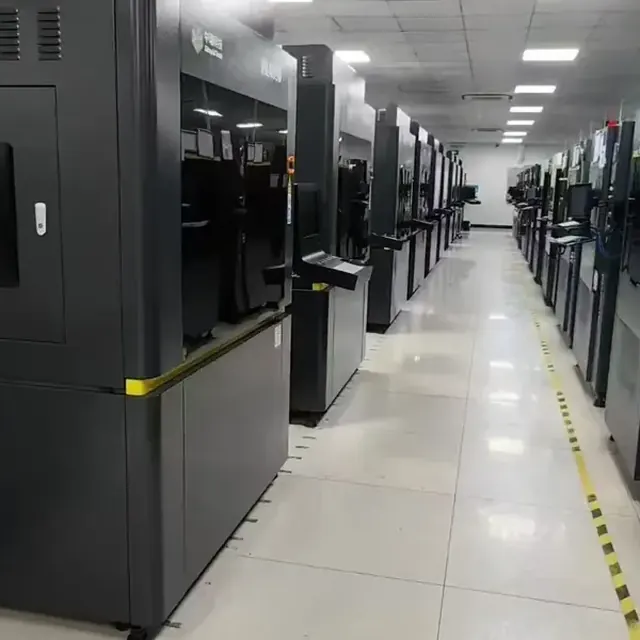
CNC turning is a subtractive manufacturing process. The workpiece is clamped in a chuck and rotates at high speed. Cutting tools on a tool turret feed along the X and Z axes, removing material layer by layer until the required geometry is formed. The full cycle is controlled precisely by computer programs (G-code).
Core difference vs milling: in turning the workpiece rotates; in milling the tool rotates while the workpiece stays fixed.
| Type | Characteristics | Typical Uses |
|---|---|---|
| CNC Lathe | Basic turning with 2-axis control | Simple shafts, sleeves, stepped shafts |
| Turn-Mill | Integrated milling; turn + mill in one setup | Complex parts with eccentric holes and keyways |
| Swiss-type | Guide-bush support for slender small parts | Miniature shafts, bone screws, precision connector pins |
| Multi-spindle Lathe | Simultaneous multi-spindle machining | High-efficiency production of large batches of small parts |
Standard ±0.01 mm; high precision ±0.001–±0.002 mm
Up to 20,000 rpm
Down to about 2.0 mm
Up to 1000 mm
Mirror finishes down to Ra 0.05 μm
Simple parts 1–3 days; complex parts 7–10 days
| Operation | Description |
|---|---|
| Turning (OD) | Removes outer material to form a cylindrical surface |
| Facing | Cuts the end face to create a flat datum |
| Boring | Enlarges or finishes internal holes |
| Grooving | Cuts relief grooves, seal grooves, and similar features |
| Threading | Turns internal or external threads |
| Knurling | Presses non-slip texture onto cylindrical surfaces |
| Parting | Cuts the finished part from bar stock |
| Drilling / reaming | Drills and finishes holes on the face or centerline |
Common secondary finishes after turning include:
Corrosion protection and color for aluminum
Nickel, chrome, or gold plating for wear and appearance
Thick, durable protective coating
Corrosion protection for stainless steel
Mirror-level surface finish
Uniform matte texture
Black corrosion-resistant coating for steel
Quench, temper, anneal to improve mechanical properties
Logos, serial numbers, and identification
| Nominal size range | Plastics (ISO 2768-m) | Metals (ISO 2768-f) |
|---|---|---|
| 0.5 – 3 mm | ±0.1 mm | ±0.05 mm |
| 3 – 6 mm | ±0.1 mm | ±0.05 mm |
| 6 – 30 mm | ±0.2 mm | ±0.1 mm |
| 30 – 120 mm | ±0.3 mm | ±0.15 mm |
| 120 – 400 mm | ±0.5 mm | ±0.2 mm |
| 400 – 1000 mm | ±0.8 mm | ±0.3 mm |
| Industry | Typical Parts |
|---|---|
| Aerospace | Engine shafts, landing-gear parts, fasteners |
| Automotive | Drive shafts, gears, piston pins, steering knuckles |
| Medical devices | Bone screws, surgical instruments, implants, catheter connectors |
| Electronics & telecom | Connector pins, heat sinks, antenna masts |
| Energy | Valves, flanges, couplings, drilling components |
| Robotics / automation | Joint shafts, gears, precision transmission parts |
Turned-part cost is mainly driven by:
Large price gaps between materials (e.g. aluminum vs titanium)
Complexity and tolerance requirements drive cycle time
First-article programming and parameter tuning
Non-standard form tools when required
Surface finishes and heat treatment
Use of precision metrology equipment
Larger batches lower the unit cost
| Comparison | CNC Turning | CNC Milling |
|---|---|---|
| Motion mode | Workpiece rotates; tool feeds | Tool rotates; workpiece is fixed |
| Applicable shapes | Rotational parts: shafts, sleeves, bolts | Prismatic parts, housings, contoured surfaces |
| Typical parts | Shafts, gear blanks, threaded parts | Brackets, molds, complex cavities |
| Cost traits | High efficiency and lower cost for rotational parts | Greater flexibility for complex non-round shapes |
We use cookies to personalize your experience. By using this site, you agree to our Privacy Policy
Accept