
Internal flow paths
Channels that cannot be drilled from the outside can justify SLM, provided the design includes a practical route for depowdering, inspection, and functional testing.

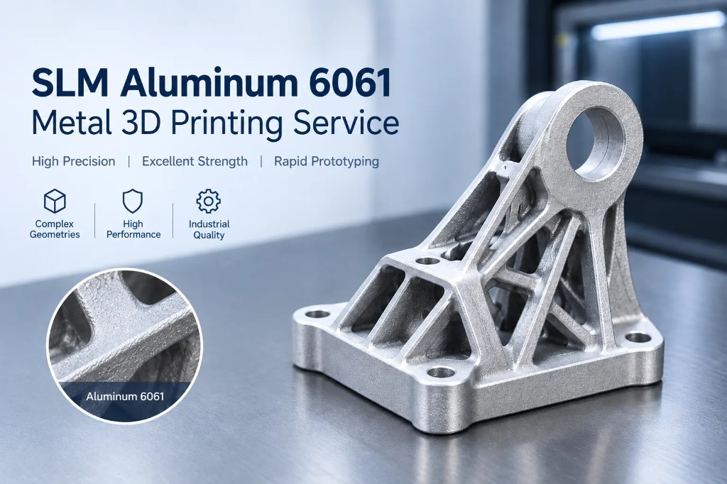
The right question is not whether a metal part looks complex. It is whether the geometry changes function, assembly, mass, or the speed of a meaningful design iteration.
Channels that cannot be drilled from the outside can justify SLM, provided the design includes a practical route for depowdering, inspection, and functional testing.
Lightweight lattices and topology-led forms are most useful when lower mass supports stiffness, thermal behavior, robot reach, or a smaller assembly envelope.
Consolidating brackets, manifolds, or interfaces can remove fasteners, seals, alignment steps, and inventory lines from a low-volume design.
SLM is a sequence of powder, laser, orientation, support, and finishing decisions. The build plan should be reviewed as a complete route, not as a print step alone.
The service page lists an as-built grainy metallic finish, with polishing, coating, or CNC finishing available when the interface or surface requirement calls for it.
| Service detail | Listed range or option |
|---|---|
| Materials | AlSi10Mg, Aluminum 6061, Ti6Al4V, Stainless 316L, Stainless 17-4 PH; tool steel and nickel alloys by project review |
| Build envelope | 420 × 420 × 450 mm |
| Listed tolerance | ±0.3 mm or ±0.3%, whichever is greater; tighter fits can be considered after machining |
| Finishing | As-built metallic finish, polishing, coating, or CNC finishing |
| Starting lead-time wording | From 5 business days; final timing depends on the selected route and project details |
SLM and CNC solve different problems. Compare the work required from released CAD to accepted part, including supports, tool access, finishing, inspection, and the value of part consolidation.
| Decision factor | SLM becomes more compelling when... | CNC may be the cleaner route when... |
|---|---|---|
| Geometry | Internal channels, organic load paths, lattices, or consolidated assemblies create measurable value. | The shape is simple, externally accessible, and already suited to stock removal. |
| Quantity | The project is a prototype, service spare, engineering lot, or small batch where dedicated tooling would add friction. | Repeat quantity allows setup, programming, and workholding effort to spread across many parts. |
| Finishing | Supports, depowdering, heat treatment, and selective machining are planned into the acceptance route. | Fine surface finish is required across many exposed faces or is difficult to inspect after printing. |
| Risk review | The team can define material, orientation, critical fits, powder access, and inspection evidence before release. | The part has known stock behavior and a mature machining route with fewer process questions. |
Blind cavities and narrow channels need an intentional removal path rather than a CAD-only assumption.
Call out fits and threads that may need secondary machining instead of treating the as-built surface as final.
Orientation affects supports, thermal stress, rough surfaces, build time, and the ability to clean the finished part.
A useful quote starts with the part and its acceptance conditions. Share the inputs below so the build route can be reviewed without guessing at the design intent.
Send the current STL, STEP, or other supported CAD file, plus the overall size and any features that must remain within the listed build envelope.
Name the preferred alloy or the load, heat, corrosion, and weight conditions that should guide the material review.
Mark datum faces, threads, mating surfaces, sealing areas, and the dimensions that need machining or inspection after the build.
State the required surface treatment, inspection expectations, quantity, destination, and whether the part is a prototype, spare, or repeat batch.
These AIHFABS articles add practical context for comparing routes, setting application boundaries, and discussing repeatability with the project team.
Use geometry, batch economics, finishing effort, and verification risk to compare the complete manufacturing route instead of the quoted unit price alone.
Read the route comparisonMap common engineering contexts to geometry and material questions while keeping application language separate from project-specific qualification.
Review the application boundariesFrame the conversations around near-full density, dimensional control, process qualification, and the evidence needed for repeat production.
Review the acceptance factorsUse these answers to narrow the design conversation before uploading a model or discussing a special specification.
SLM is a strong candidate when the geometry creates functional value through internal channels, lightweight structures, lattices, or assembly consolidation, especially for low-volume functional parts.
The SLM service lists Aluminum AlSi10Mg, Aluminum 6061, Titanium Ti6Al4V, Stainless 316L, Stainless 17-4 PH, and project-reviewed tool steel or nickel alloys.
The listed build envelope is 420 × 420 × 450 mm. The listed tolerance is ±0.3 mm or ±0.3%, whichever is greater; tighter fits can be considered through machining.
As-built SLM parts have a grainy metallic finish. Polishing, coating, or CNC finishing can be reviewed when the application needs a different surface or more precise interface.
Plan access for powder removal in blind cavities and narrow channels. Unsupported overhangs below about 45 degrees need careful review, with supports, fillets, or lattice transitions considered where appropriate.
Send the CAD model, target material, quantity, critical dimensions or fits, application conditions, finishing needs, inspection expectations, and destination details so the route can be reviewed against the part.
Upload the CAD model for a process and material comparison, or contact AIHFABS when the project includes unusual geometry, finishing, inspection, or application requirements.
We use cookies to personalize your experience. By using this site, you agree to our Privacy Policy
Accept