
3D Printing
Stereolithography (SLA)
Stereolithography (SLA) cures liquid photopolymer with a precision UV laser, building parts layer by layer.
Create a quote
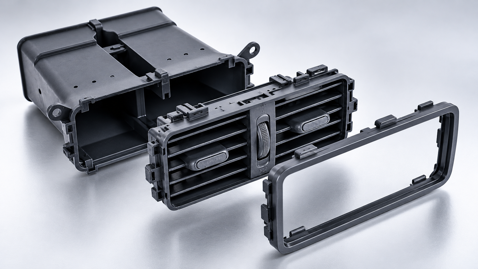
SLA can reproduce fine details and smooth surfaces, but a detailed CAD model is only the starting point. A thin wall must survive cleaning and handling. A locating pin must fit its mating hole after curing. A hollow enclosure must allow liquid resin to leave, and its visible surfaces must remain accessible for finishing.
Good design for stereolithography connects these requirements before printing begins. Start with what the finished part must do, then work through geometry, assembly, build preparation, and inspection. This SLA design guide follows that sequence so you can identify the features that need attention before requesting a quote.
The same enclosure may be suitable for an appearance review yet unsuitable for repeated assembly. Before changing wall thickness or adding clearance, identify what the prototype needs to demonstrate: appearance, fit, movement, load resistance, or a combination of these.
Mark the visible faces, mating surfaces, locating features, and dimensions that determine whether the part works. Also state whether those dimensions apply after washing and post-curing or after additional sanding, painting, or coating. A supplier cannot infer these priorities reliably from the solid model alone.
Material selection belongs at this stage. A clip that bends during assembly needs a different combination of material properties and geometry from a rigid display shell. Use the SLA resin selection guide to identify suitable candidates before finalizing delicate or loaded features.
Use the following review order to turn the requirements into design decisions.
Review stage | Question to resolve | What to specify or change |
Function | What must the finished part prove? | Material requirements, loads, appearance, and acceptance criteria |
Geometry | Will small features survive the complete workflow? | Walls, ribs, holes, pins, and lettering |
Assembly | Will mating parts fit across dimensional variation? | Datums, tolerances, clearances, and finish allowances |
Build preparation | Can the part be supported and cleaned? | Critical faces, support access, cavities, and drainage |
Delivery | Can the result be checked against the design? | Current CAD revision, drawing, finish specification, and inspection dimensions |
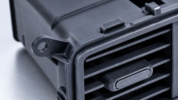
A minimum printable wall is a manufacturing limit, not a structural recommendation. A short wall attached along several edges behaves differently from a broad, free-standing panel of the same thickness. Consider its height, unsupported span, curvature, handling loads, and connection to the surrounding geometry.
For a large enclosure, review whether ribs, a return flange, or local reinforcement would provide stiffness more efficiently than increasing the thickness everywhere. Add reinforcement where the load enters the part, such as around mounting points, and avoid abrupt transitions into thin sections. Keep access for support removal and cleaning when placing internal ribs.
For flexible tabs, thickening is not automatically an improvement. A stiffer tab may require more insertion force and concentrate strain at its root. Review the material, bending length, thickness, and root radius together, then test the feature under the intended movement.
A shallow hole and a long narrow bore with the same diameter present different manufacturing challenges. Identify whether each hole is decorative, a clearance hole, a locating feature, or a passage that must remain open. Deep blind holes and narrow channels also need a practical cleaning route.
For pins, consider height as well as diameter. Protect slender projections from support-removal tools and handling loads. If a small pin must repeatedly locate an assembly or resist wear, consider whether a separate insert is more appropriate than an integral resin feature.
For lettering, specify stroke width and relief height or engraving depth rather than relying only on font size. Leave room between strokes and surrounding features. If the part will be painted, review whether primer and finish coats could soften the detail.
Published SLA design guidelines are useful when their scope is clear. The examples below come from Formlabs testing with Clear Resin on a Form 2 at a 100 µm layer height. They illustrate feature-specific limits.
Feature | Published reference minimum | How to interpret it |
Supported or unsupported wall | 0.4 mm | A printability reference for the stated setup, not a load-bearing wall specification |
Hole diameter | 0.8 mm | Does not establish the tolerance or cleanability of a deep passage |
Embossed detail | 0.1 mm wide and 0.1 mm high | Evaluate finished legibility separately |
Engraved detail | 0.4 mm wide and 0.4 mm deep | Recessed and raised details have different limits |
Clearance between parts in the same model | 0.5 mm | Intended to prevent fusion during printing, not to define every assembled fit |
Drain hole diameter | 3.5 mm | An opening must also serve the cavity and its drainage route |
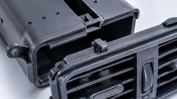
Two parts can look correct individually and still fail to assemble. For mating features, distinguish three quantities: the nominal CAD dimensions, the permitted dimensional variation, and the clearance required for movement or installation.
Layer height is a separate parameter. It describes the vertical increment used to build the part; it is not a guarantee that a hole, pin, or overall length will be accurate to that value. Specify the critical finished dimensions on a drawing and identify the surfaces from which they should be measured.
Consider an illustrative pin-and-hole assembly. Suppose the pin is 10.00 ± 0.20 mm and the hole is 10.50 ± 0.20 mm. These are assumed design values for this calculation, not a tolerance commitment for a particular job.
Fit calculation | Dimensions used | Result |
Nominal diametral clearance | 10.50 − 10.00 mm | 0.50 mm |
Minimum diametral clearance | Smallest hole 10.30 − largest pin 10.20 mm | 0.10 mm |
Maximum diametral clearance | Largest hole 10.70 − smallest pin 9.80 mm | 0.90 mm |
The nominal gap alone hides a wide range of possible fits. For a centered, round pin and hole, the corresponding radial clearance is half the diametral value. Hole form, alignment, and surface condition may further affect assembly.
If the permissible movement cannot accommodate this range, increasing the nominal gap will not solve both tightness and looseness. You may need a tighter manufacturing tolerance, a different locating arrangement, a secondary finishing operation, or a small fit trial before ordering the full set.
Define whether mating surfaces will be coated, masked, or left in the agreed printed finish. Coating a pin increases its outside diameter; coating a bore reduces its inside diameter. Both changes reduce clearance.
Keep the required finished dimensions clear in the design record. Do not apply a blanket shrinkage allowance to the entire model unless it forms part of an agreed compensation method. Otherwise, compensation in the CAD file and compensation during build preparation may overlap.
For reference, the AIHFabs SLA printing service currently describes typical tolerances around ±0.2 mm on well-supported features. Treat this as an initial planning reference; critical dimensions, material, geometry, and delivery condition belong in the project review.
Orientation affects which features need support, where contact marks appear, and how the part behaves during printing. It also changes the sequence in which sections form. Manufacturer guidance therefore treats orientation as a geometry-dependent decision. Start by identifying surfaces where support contact would be most disruptive: visible covers, sealing lands, locating faces, and small functional details. Mark these on a drawing or annotated image. Then identify less sensitive areas where support contact and local finishing are acceptable.
Check removal access as carefully as support placement. A support inside a narrow passage may be difficult to reach without damaging the part. Changing the orientation, opening the passage, or separating the design into components may be more practical. Formlabs also recommends planning support contact around surface finish and removal access.
A fixed rule such as “all overhangs below 45° require supports” is too broad for a general SLA design guide. The angle reference, material, overhang length, surrounding geometry, and machine all matter. For bottom-up systems, separation from the tank surface adds another consideration. The build should be reviewed for isolated starting features, long unsupported regions, and abrupt changes in cross-section.
For an enclosure, the useful design instruction is specific: preserve the front cosmetic face and the locating ledge, while allowing support contact on designated rear or internal areas. This gives build preparation a clear objective without prescribing one orientation for every machine.
Hollowing can reduce material use, but an enclosed void in a resin print is not automatically an empty cavity. Liquid resin can remain trapped unless the geometry provides an effective exit. Formlabs also identifies enclosed hollows as a source of suction-cup problems in bottom-up printing.
Inspect a section view of the model. Check each cavity separately, including pockets created by ribs, internal partitions, and joined bodies. One opening on the outside does not guarantee that every internal region connects to it.
Position openings for the planned printing, draining, and washing orientations. Where a single hole would restrict flow or air exchange, provide another opening or a larger accessible passage. Hole diameter alone cannot compensate for a blind pocket or a long, obstructed route.
Plan how the inside will be cleaned, checked, and post-cured where required by the material workflow. If access is inadequate, an open-backed design or a split shell may be preferable. If openings will later be plugged, define that finishing step only after the internal processing requirements have been met.
Assess the total job rather than resin consumption alone. Added cleaning, internal support removal, plugging, and finishing may offset material savings. Hollowing should have a clear purpose: weight reduction, access, function, or an evaluated manufacturing benefit.
Splitting can help when a part exceeds the usable build envelope or when separate sections allow better support access and surface placement. The joint then becomes a design feature that must be located, assembled, and inspected.
Place seams where they can be reached for bonding and finishing, and avoid crossing a critical datum or an important cosmetic detail unnecessarily. Add identifiers if similar sections could be confused during assembly.
Pins, slots, lips, or other locating features can assist alignment, but they also introduce dimensional requirements. Multiple tight locators may prevent assembly when printed sections vary. Formlabs' large-model guidance describes this trade-off between self-aligning joints and simpler cuts that require external alignment during bonding.
Define the bond-line allowance for the chosen joint and adhesive rather than applying one universal gap. Provide space to apply adhesive and hold the assembly without damaging thin walls. Inspect overall alignment and critical dimensions after bonding; acceptable individual sections do not automatically create an acceptable finished assembly.
A useful manufacturing package includes the model and the information needed to interpret it. Supply the current revision, identify the units, and provide a drawing for critical dimensions, datum references, finish requirements, and assembly interfaces.
For mesh files, inspect the exported file rather than assuming it matches the CAD display. Curves represented by coarse triangles can retain visible faceting. Check for missing faces, intersecting surfaces, and unintended disconnected bodies. Protolabs' STL guidance explains the relationship between mesh resolution and how the exported model represents the intended shape.
Run a final review against the finished part requirements.
Final check | Evidence to include or verify |
Material and purpose | Selected resin or required properties, intended test, and use conditions |
Small features | Wall spans, fragile projections, open holes, and readable details |
Fit and measurement | Mating dimensions, clearance calculation, datums, and inspection condition |
Supports and cavities | Marked critical faces, removal access, connected drainage, and internal processing access |
Finishing and assembly | Coating or masking notes, joint design, hardware, and assembled inspection dimensions |
File consistency | Matching revisions, declared units, valid geometry, and quantities |
This review is a rehearsal of the manufacturing process in CAD. Its purpose is to expose a blocked drain, inaccessible support, or unsuitable fit while the solution is still a model change.
Consider a hypothetical two-piece electronics enclosure with a visible front cover, internal locating pins, and a removable rear panel. The first review might focus on the outside shape. Preparing it for manufacture requires a different set of decisions.
Mark the front as the cosmetic face and identify the ledge that controls panel position. Review broad wall spans separately from local details, and reinforce mounting areas where needed. Calculate the pin-and-hole fit using the intended finished dimensions. Keep coating off selected mating surfaces if the finish would consume the available clearance.
Next, check whether supports can be removed from the internal features. Inspect any hollow regions for isolated pockets and provide a cleaning route. If the enclosure is split for printing, place the joint where alignment and finishing can be controlled.
The result is a CAD package with measurable requirements: which surfaces matter, how the parts should fit, where finishing is allowed, and what must be inspected. A first sample can then answer those questions before the design is released for a larger quantity.
SLA does not require draft for release from a conventional injection mold. Draft may still belong in the model when the printed part represents a future molded design or will serve as a molding pattern. Deep cavities need support-removal and cleaning access; adding a nominal draft angle alone does not provide that access.
Some geometries permit this, but the gaps must remain open, resin must be removable, and any internal supports must be accessible. Separately printed components are often easier to inspect and finish. Use a small representative test when movement depends on a narrow printed gap.
Prioritize the dimensions and geometric relationships that control function. Broadly applying tight requirements can add work without improving the result. Identify the necessary fit, alignment, flatness, or appearance requirement and agree how it will be verified.
Ready to review your design for manufacture? Explore AIHFabs' SLA printing service for custom resin parts, then upload your CAD files for a quote. Include your preferred material, quantity, critical dimensions, cosmetic faces, and required finish so the project can be assessed against the part's actual requirements.
If a wall, fit, cavity, or assembly detail still needs a decision, contact our team with the model and an annotated drawing.
1. Formlabs. Design specifications for 3D models — Form 2. Source of the explicitly qualified feature-size examples.
2. Protolabs. 7 Mistakes to Avoid When Designing 3D-Printed Parts. Feature size, resolution, and geometry considerations.
3. Formlabs. Model orientation best practices for SLA printing. Orientation, support, and build-stability considerations.
4. Formlabs. Advanced support removal techniques. Preserving functional and cosmetic features during support removal.
5. Formlabs. Hollowing models in PreForm. Hollow geometry, drainage, and trapped-material considerations.
6. Formlabs. How to Create Models Larger Than Your 3D Printer's Build Volume. Model splitting and alignment options.
7. Protolabs. How to Design STL Files for 3D Printing in Your CAD Program. Mesh preparation and export considerations.

A process that fits this note. Open the spec, or put the file on a quote.
Stereolithography (SLA) cures liquid photopolymer with a precision UV laser, building parts layer by layer.
Create a quote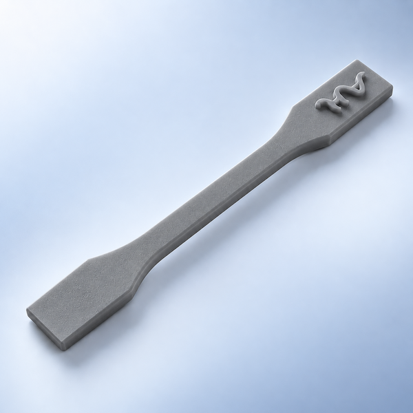
Digital Light Processing (DLP) solidifies an entire layer of photopolymer at once using a projected image.
Create a quoteMaterials that sit next to this article. Check the card, then upload CAD.
Process, finish, and file notes from the shop — not a marketing blog.
Company, payment, shipping, and process answers by topic.
Questions about 3D printing processes, materials, MOQ, samples, and custom projects.

AIHFABS quotes custom 3D printing and CNC machining from a CAD upload. Compare SLA, SLS, MJF, SLM, FDM, DLP, milling, and turning, then add finishing such as vapor smoothing, dyeing, anodizing, polishing, or powder coating in the same order.
Instant quoting is built for prototypes, jigs, housings, and small-batch production. You see material, process, quantity, and lead time together, which keeps engineering changes from turning into a new round of supplier emails.
You can review material, process, quantity, and lead time together, so engineering changes do not turn into another round of supplier emails.
Upload STL, STEP, and other common CAD formats for an online quote.
Compare 3D printing technologies and CNC options on the same part.
Select polymers or metals, then add 3D Plus hardware finishing when needed.
Review price and lead time before checkout, or request a manual quote for special specs.
If this page describes a process, industry, or sample part you want to reproduce, start from the upload flow and match technology plus finishing to your drawing.
We use cookies to personalize your experience. By using this site, you agree to our Privacy Policy
Accept

Leave A Comment